
Hard alloy mould labeling equipment

A cemented carbide and mold technology, which is applied in the field of cemented carbide mold labeling equipment, can solve the problems of affecting the labeling process, uncontrollable label paper force, and looseness, and achieves easy fixing, wide range of distance adjustment, and easy adjustment. Effect

Inactive Publication Date: 2015-12-09
TIANJIN MIGE TECH DEV
View PDF0 Cites 1 Cited by
  • Summary
  • Abstract
  • Description
  • Claims
  • Application Information

AI Technical Summary

Problems solved by technology

At present, there is no tension control device between the winding wheel and the unwinding wheel of the labeling equipment, the tension of the label paper cannot be controlled, and slack often occurs, which affects the normal operation of the labeling process

Method used


Image

  • Hard alloy mould labeling equipment

Examples


Embodiment

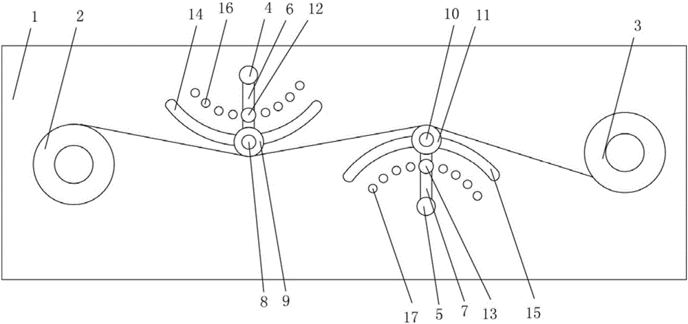
[0018] like figure 1 As shown, a cemented carbide mold labeling equipment includes a fixed plate 1, a winding wheel 2, an unwinding wheel 3, a first rotating shaft 4, a second rotating shaft 5, a first connecting rod 6, a second connecting rod 7, The first roller shaft 8, the first roller 9, the second roller shaft 10, the second roller 11, the first screw 12, the second screw 13, the winding wheel 2 is installed on one end of the fixed plate 1, and the unwinding wheel 3 is installed on the At the other end of the fixing plate 1, the fixing plate 1 is provided with a first slot 14 and a second slot 15. The first slot 14 and the second slot 15 are arc structures with opposite bending directions. The first slot 14 , The second slot 15 is located between the rewinding wheel 2 and the unwinding wheel 3 in turn, the first rotating shaft 4 is installed on the fixed plate 1 and is located on one side of the first slot 14, and the first rotating shaft 4 is located in the first opening...


PUM


Abstract

The invention belongs to the field of mould processing equipment, in particular to hard alloy mould labeling equipment. The hard alloy labeling equipment is characterized in that a first open slot and a second open slot are sequentially positioned between a winding wheel and an unwinding wheel; a first rotary shaft is positioned at one side of the first open slot; a second rotary shaft is positioned at one side of the second open slot; one end of a first connecting rod is mounted on the first rotary shaft, and the other end of the first connecting rod is mounted in the first open slot; one end of a second connecting rod is mounted on a second rotary shaft and the other end of the second connecting rod is mounted in the second open slot; a first roller wheel is mounted on a first roller wheel shaft; a second roller wheel shaft is mounted at the other end of the second connecting rod; a first fixed hole is formed in a fixed plate; a first bolt penetrates through the first connecting rod and then is mounted in the first fixed hole; a second fixed hole is formed in the fixed plate; and a second bolt penetrates through the second connecting rod and then is mounted in the second fixed hole.

Description

technical field [0001] The invention belongs to the field of mold processing equipment, in particular to a hard alloy mold labeling equipment. Background technique [0002] Cemented carbide molds are ten times or even dozens of times longer than steel molds. Cemented carbide molds have high hardness, high strength, corrosion resistance, high temperature resistance and small expansion coefficient. Generally, tungsten-cobalt carbide is used. Carbide dies often have: cold heading dies, cold punching dies, wire drawing dies, hexagonal dies, spiral dies, etc. Cemented carbide dies can be divided into four categories according to their uses: the first category is cemented carbide wire drawing dies, which account for the vast majority of cemented carbide dies; the second category of dies is cold heading cold punching dies and shaping dies; the third The first type of mold is a non-magnetic alloy mold for the production of magnetic materials; the fourth type is a hot working mold. ...

Claims


Application Information

Patent Timeline
Patent Type & Authority Applications(China)
IPC IPC(8): B65C9/18B65H23/26
Inventor 张卓
Owner TIANJIN MIGE TECH DEV
Learn More