
Automatic tube rod conveying machine

An automatic conveying and pipe-rod technology, applied in drill pipe, drill pipe, casing, etc., can solve the problems of not being applicable to small workovers and inability to carry out small workover operations, and achieve the effects of low production cost, convenient maintenance, and reduced investment.

Inactive Publication Date: 2015-12-09
JIANGSU SHENLIDA MACHINERY MFR
View PDF11 Cites 5 Cited by
  • Summary
  • Abstract
  • Description
  • Claims
  • Application Information

AI Technical Summary

Problems solved by technology

[0003] see figure 1 , figure 1 A pipe rod conveyor in the prior art is disclosed. The working principle of the pipe rod conveyor in the prior art is as follows: the rocking rod 1 is pushed by the lifting cylinder 2, and when the rocking rod 1 swings at an angle, the upper part of the entire frame is caused to (The two-section frame 3) rises as a whole, and stops when it rises to a predetermined height; then it starts to move obliquely, that is, the V-shaped pipe groove 5 is pushed by the propulsion cylinder 4, and the V-shaped pipe groove 5 is smoothly sent to the wellhead, so that it is convenient For worker operation, please refer to Chinese Patent Announcement No. CN203783493U, Chinese Patent Announcement No. CN203603787U, Chinese Patent Announcement No. CN203499592U and Chinese Patent Announcement No. CN202832293U. The pipe rod conveyors involved in the above four patents are all like this structure, the defect of this kind of pipe and rod conveyor in the prior art is that it can only be applied to a major workover with a platform, but not to a small workover, because there is no workover platform in a small workover, and oil field workover workers are standing For ground operations, if the conveyor moves the pipe rods very high, the oilfield operators cannot pick up or lift the elevators at all, so minor repairs cannot be carried out.

Method used


Image

  • Automatic tube rod conveying machine
  • Automatic tube rod conveying machine
  • Automatic tube rod conveying machine

Examples


Embodiment Construction

[0021] In order to make the object, technical solution and advantages of the present invention clearer, the specific implementation manners of the present invention will be described in detail below in conjunction with the accompanying drawings. Examples of these preferred embodiments are illustrated in the accompanying drawings. The embodiments of the invention shown in and described with reference to the drawings are merely exemplary, and the invention is not limited to these embodiments.

[0022] Here, it should also be noted that, in order to avoid obscuring the present invention due to unnecessary details, only the structures and / or processing steps that are closely related to the solution according to the present invention are shown in the drawings, while those related to the present invention are omitted. Other details are not relevant to the invention.

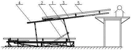
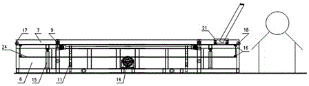
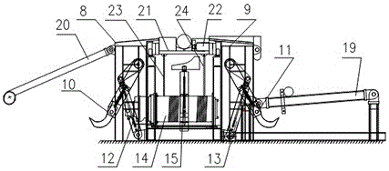
[0023] ginseng figure 2 and image 3 As shown, a pipe rod automatic conveyor includes: a frame 6 and a car groov...


PUM


Abstract

The invention discloses an automatic tube rod conveying machine which comprises a rack, a lathe groove, an upper unloading frame, a feeding hook frame, a feeding oil cylinder, a winch, a material jacking oil cylinder and pulley mechanisms, wherein the lathe groove, the upper unloading frame, the feeding hook frame, the feeding oil cylinder, the winch, the material jacking oil cylinder and the pulley mechanisms are arranged on the rack. The feeding hook frame is driven by the feeding oil cylinder to swing up and down. One end of the rack is provided with a first sliding roller, and the other end of the rack is provided with a second sliding roller. One side of the rack is provided with a feeding pipe bridge, and the other side of the rack is provided with an unloading pipe bridge. The lathe groove is formed in the upper portion of the rack. The lathe groove is internally provided with a tube conveying trolley and a tube conveying trolley limiting device. The tube conveying trolley is internally provided with a clamping oil cylinder. Steel wire ropes are wound around the winch, tensioned by the pulley mechanisms and then connected with the tube conveying trolley. The automatic tube rod conveying machine is low in production cost, safe, reliable, convenient to maintain and easy to popularize and solves the problem that an existing conveying machine can only be applicable to a big workover with a platform but cannot be applicable to a small workover.

Description

technical field [0001] The invention relates to an automatic conveying machine for pipe rods. Background technique [0002] As we all know, in the workover site of oil drilling and workover, the automatic pipe and rod conveyor is gradually promoted to realize the transmission of pipe and rod (oil pipe, tools, drill pipe, etc.) from the wellhead to the pipe bridge. It has high working efficiency, well protects the threaded thread of the pipe, and is safer than the previous manual pulling of the pipe. [0003] see figure 1 , figure 1 A pipe rod conveyor in the prior art is disclosed. The working principle of the pipe rod conveyor in the prior art is as follows: the rocking rod 1 is pushed by the lifting cylinder 2, and when the rocking rod 1 swings at an angle, the upper part of the entire frame is caused to (The two-section frame 3) rises as a whole, and stops when it rises to a predetermined height; then it starts to move obliquely, that is, the V-shaped pipe groove 5 is ...

Claims


Application Information

Patent Timeline
IPC IPC(8): E21B19/14
Inventor 张秀红
Owner JIANGSU SHENLIDA MACHINERY MFR
Features
  • Generate Ideas
  • Intellectual Property
  • Life Sciences
  • Materials
  • Tech Scout
  • Unparalleled Data Quality
  • Higher Quality Content
  • 60% Fewer Hallucinations
Learn More