Draught fan bearing pedestal

A bearing seat and fan technology, applied in mechanical equipment, machines/engines, liquid fuel engines, etc., can solve the problems of motor fan burnout, fan heat cannot be dissipated, etc., to maintain effectiveness and increase heat transfer area , to ensure the effect of service life

Inactive Publication Date: 2015-12-09
天津尼特风机有限公司
View PDF0 Cites 0 Cited by
  • Summary
  • Abstract
  • Description
  • Claims
  • Application Information

AI Technical Summary

Problems solved by technology

[0002] The fan mainly drives the rotating shaft to rotate through the motor, and the other end of the rotating shaft is connected to the impeller, thereby driving the impeller to rotate. When the impeller rotates for a long time, a large amount of heat will be generated

Method used


Image

  • Draught fan bearing pedestal
  • Draught fan bearing pedestal

Examples


Embodiment Construction

[0015] The specific implementation manners of the present invention will be described in detail below in conjunction with the accompanying drawings.

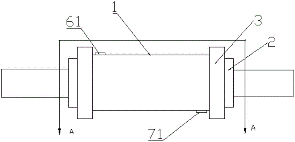
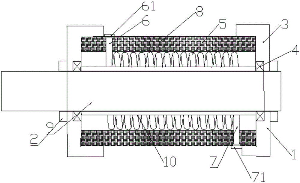
[0016] Such as figure 1 , figure 2 As shown, the present invention provides a fan bearing housing, including a base body 1, end covers 2 located at both ends of the base body 1, a bearing chamber 3 inside the end cover 2, and a bearing 4 located in the bearing chamber 3 A through hole 9 provided axially along the base body 1 for the shaft to pass through, characterized in that: a ring-shaped heat conduction plate 10 is arranged inside the base body 1, and a spiral-shaped heat conduction plate 10 is arranged around the heat conduction plate 10. A water pipe, the two ends of the water pipe are respectively provided with a water inlet pipe 6 and an outlet pipe 7, the water inlet pipe 6 extends upward to the outer surface of the base 1, and the outlet pipe 7 extends downward to the base 1 A heat insulator 8 is provided between th...


PUM


Abstract

The invention provides a draught fan bearing pedestal. The draught fan bearing pedestal comprises a base body, end covers located at the two ends of the base body, bearing chambers inside the end covers, bearings located in the bearing chambers, and through holes for a rotating shaft to penetrate through in the axial direction of the base body. The draught fan bearing pedestal is characterized in that a circular ring type heat conduction plate is arranged in the base body, a spiral water pipe surrounds the heat conduction plate, a water inlet pipe and a water outlet pipe are arranged at the two ends of the water pipe respectively, the water inlet pipe extends to the outer surface of the base body upwards, the water outlet pipe extends to the outer surface of the base body downwards, and thermal insulation cotton is arranged between the water pipe and the inner wall of the base body. By means of the draught fan bearing pedestal, the rotating shaft can be cooled, the heat transfer area is enlarged through the water pipe arranged in a spiral mode, heat of a draught fan is prevented from being transmitted to a motor through the rotating shaft and burning down the motor, and the service life of the motor and the draught fan is ensured.

Description

technical field [0001] The invention belongs to the field of fan equipment, and in particular relates to a fan bearing seat. Background technique [0002] The fan mainly drives the rotating shaft to rotate through the motor, and the other end of the rotating shaft is connected to the impeller, thereby driving the impeller to rotate. When the impeller rotates for a long time, a large amount of heat will be generated at the impeller bearing, which will be transmitted to the motor through the rotating shaft. It also generates heat, so long-term operation prevents the heat of the entire fan from being dissipated, and it is easy to burn out the motor or the entire fan. Contents of the invention [0003] In order to solve the above technical problems, the technical solution adopted in the present invention is: a fan bearing housing, including a base body, end covers located at both ends of the base body, a bearing chamber inside the end cover, and a bearing located in the bearin...

Claims


Application Information

Patent Timeline
IPC IPC(8): F04D29/056F04D29/58
Inventor 孙富长
Owner 天津尼特风机有限公司
Why Eureka
Try Eureka