Designing method of cylindrical blade with controllable inlet setting angle

A design method and a technology of placing angles, which are applied to mechanical equipment, parts of pumping devices for elastic fluids, non-variable pumps, etc., can solve the problem of reducing water flow pressure, limiting the use range of cylindrical blades, and blade inlet impact Loss and other issues

Inactive Publication Date: 2015-12-09
XIHUA UNIV
View PDF4 Cites 7 Cited by
  • Summary
  • Abstract
  • Description
  • Claims
  • Application Information

AI Technical Summary

Problems solved by technology

The two-dimensional cylindrical blade has the outstanding advantages of simple structure, convenient manufacture, and low scrap rate during processing. However, numerous experiments have shown that when the geometric conditions such as the impeller and volute are constant, the pump will be at the design speed and design flow rate. In the downtime operation, the efficiency of the cylindrical blade is 1-2% lower than that of the three-dimensional twisted blade. This difference comes from the long-term design principles and methods of the cylindrical blade. If the design principle of this blade is not innovated, in fact It will be difficult to fundamentally change the efficiency index of the blade
These new planar curves either improve the curvature radius of the curve and the changing law of the curve placement angle to prevent water flow from the blade surface, or adjust the diffusion degree of the flow channel between the blades by controlling the blade wrap angle. It is meaningful to reduce the hydraulic loss in the impeller, but it does not eliminate the root cause of the relatively low hydraulic efficiency of cylindrical blades.
[0007] From the above-mentioned traditional design principles of cylindrical blades, it can be seen that in order to form the blade projection on the axial vertical plane, it is necessary to calculate the intersection point of the blade inlet edge and the back streamline in the blade axial plane projection diagram in advance, that is, figure 1 Blade placement angle β at point B 1B , and further calculate the projection value β of this angle on the axis vertical plane 1B (t), so the inlet angle of the final formed blade at point B can meet the reasonable requirement value, however, at the intersection point A of the inlet edge of the blade and the front streamline ( figure 1 ) blade placement angle is formed naturally, in the design process, the blade angle here is not even calculated at all
As a result, when the formed blade works under the design flow rate, the blade angle at point A on the blade inlet side and everywhere along the blade inlet side cannot adapt to the incoming flow direction, and the difference between the blade placement angle and the inlet relative liquid flow angle is The angle of attack is often too large, resulting in significant impact losses at the blade inlet
This phenomenon does not exist at the inlet of the twisted three-dimensional blade, which is the main reason for the relatively low efficiency of the cylindrical blade
At the same time, since the back of the blade inlet at A is a low-pressure area where cavitation bubbles are easy to form, the excessive impact loss further reduces the pressure energy of the water flow at this location, increasing the probability of cavitation
The higher the specific speed of the impeller, the more spacious the impeller flow channel on the axial plan, and the more obvious this large attack angle effect, which also limits the application range of cylindrical blades with good process performance. For a long time, this is rarely used This type of blade is used for the medium and high specific speed impellers whose specific speed exceeds 80

Method used


Image

  • Designing method of cylindrical blade with controllable inlet setting angle
  • Designing method of cylindrical blade with controllable inlet setting angle
  • Designing method of cylindrical blade with controllable inlet setting angle

Examples


Embodiment Construction

[0057] The technical solution of the present invention will be further described in detail below in conjunction with the accompanying drawings, but the protection scope of the present invention is not limited to the following description.

[0058] In order to achieve the design goals and principles of the new cylindrical blade, the blade design should be completed according to the following calculation and drawing process, which is quite different from the traditional cylindrical blade design steps.

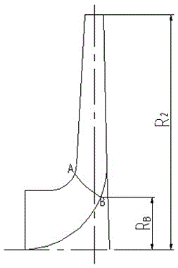
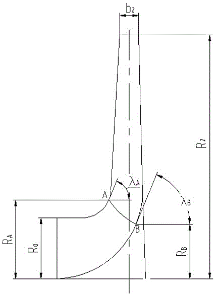
[0059] (1) According to the main geometric parameters of the blade obtained in the previous calculation, including the impeller radius R 2 , the impeller outlet width b 2 , impeller inlet radius R 0 etc. After repeated revisions and checks, a satisfactory projection of the axial plane of the blade was obtained. According to certain principles, draw the blade inlet edge on the blade axial plane projection diagram, and measure the distance R from the intersection point A and B of...


PUM


Abstract

The invention discloses a designing method of a cylindrical blade with the controllable inlet setting angle. A designing and shape drawing process of a novel cylindrical blade is given. The inlet edge of the novel blade and the blade inlet attack angle at the intersection of a front cover plate and a rear cover plate can both be given. The impact hydraulic loss at the positions of the blade inlet can be reduced through the controllable inlet setting angle, the major reason for the large hydraulic loss of a traditional cylindrical blade is eliminated, and the purpose of increasing the blade energy index is achieved. The anti-cavitation capability of the blade can be improved through the blade structure, and the application range of the cylindrical blade is enlarged. After the blade is used in an impeller with the specific speed reaching 120, a pump can still have high hydraulic efficiency.

Description

technical field [0001] The invention relates to a design method of a centrifugal pump impeller blade, in particular to a design method of a cylindrical blade with a controllable inlet placement angle. Background technique [0002] Among the millions of pump products in the country every year, the output of centrifugal pumps accounts for the majority. The external characteristics of high head and low flow rate of low specific speed centrifugal pump determine that this type of pump plays an irreplaceable role in various sectors of the national economy. This type of pump constitutes a special category of centrifugal pump products, and its output value occupies the largest share of pump products. proportion that cannot be underestimated. [0003] The centrifugal pump works on the water flow through its impeller, increases the mechanical energy of the flow, and realizes the basic function of the pump. The performance of the impeller is a key factor in determining the economic an...

Claims


Application Information

Patent Timeline
Patent Type & Authority Applications(China)
IPC IPC(8): F04D29/24
Inventor 严敬周绪成宋文武罗大明符杰
Owner XIHUA UNIV
Why Eureka
Try Eureka