
Self-lubrication sealing structure for gear box

A sealed structure, self-lubricating technology, applied in the direction of gear lubrication/cooling, belt/chain/gear, transmission parts, etc., can solve the problems of inability to achieve support bearing lubrication, inapplicability, etc.

Active Publication Date: 2015-12-09
CHANGZHOU RUITAI ENG MASCH CO LTD +1
View PDF6 Cites 9 Cited by
  • Summary
  • Abstract
  • Description
  • Claims
  • Application Information

AI Technical Summary

Problems solved by technology

This technical solution is only suitable for urban railways, subways and other occasions where the startup acceleration is fast and there is no low-speed continuous operation. The gearbox cannot realize the lubrication of its support bearings at low speeds; therefore, it is not suitable for both high and low speed operation. Requirements for the use of gearbox lubrication and seals

Method used


Image

  • Self-lubrication sealing structure for gear box
  • Self-lubrication sealing structure for gear box

Examples


Embodiment Construction

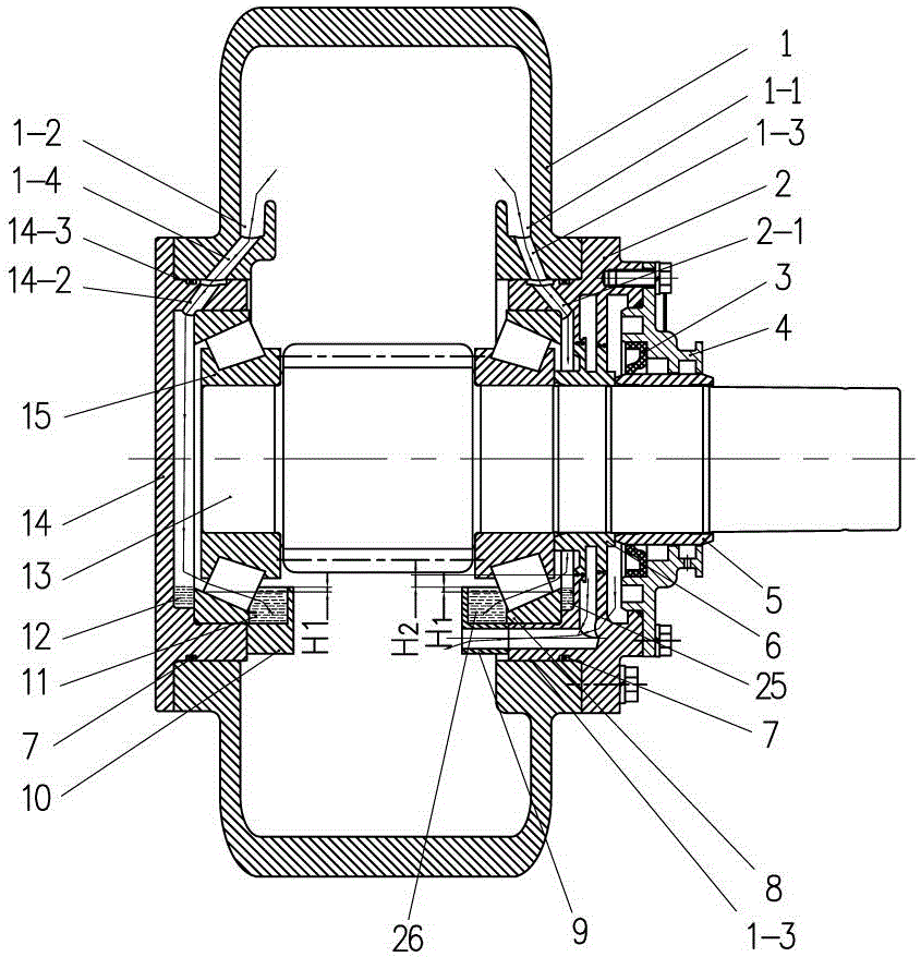
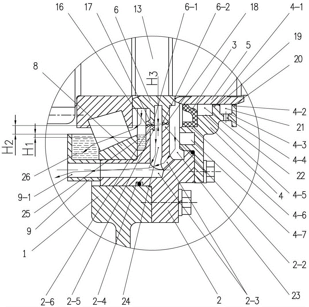
[0034] like figure 1 , 2 As shown, a gear box self-lubricating and sealing structure of the present invention includes a box body 1, a first bearing seat 2, a second bearing seat 14, a sealing ring 6, a sealing cover 4, a sliding sleeve 5, a skeleton oil seal 3, a first The support bearing 8, the second support bearing 15 and the gear shaft 13, the first bearing seat 2 and the second bearing seat 14 are respectively fixed on both sides of the casing 1, the first support bearing 8 and the second support bearing 15 respectively installed in the corresponding first bearing housing 2 and the second bearing housing 14, the gear shaft 13 is rotatably supported on the first support bearing 8 and the second support bearing 15,

[0035] On the two inner sidewalls of the box 1 and above the first bearing seat 2 and the second bearing seat 14, a first oil collecting groove 1-1 and a second oil collecting groove 1-2 are respectively provided,

[0036] The first bearing seat 2 has a firs...


PUM


Abstract

The invention discloses a self-lubrication sealing structure for a gear box. The self-lubrication sealing structure for the gear box is used on a rail transit line maintaining operation vehicle. The self-lubrication sealing structure for the gear box comprises a box body, a first bearing pedestal, a second bearing pedestal, a sealing ring, a sealing cover, a sliding sleeve, a framework oil seal, a first supporting bearing, a second supporting bearing and a gear shaft. The portions, above the first bearing pedestal and the second bearing pedestal, of the two inner side walls of the box body are provided with a first oil collecting groove and a second oil collecting groove respectively. The bottom of the first bearing pedestal and the bottom of the second bearing pedestal are fixedly connected with a first oil pool and a second oil pool respectively, and a non-contact type labyrinth sealing structure formed by combining two axial gap seals, an axial gap sealing annular groove and a radial oil swing flange, and an oil collecting lubrication structure are formed. The self-lubrication sealing structure for the gear box is compact in arrangement, simple in structure and capable of meeting the requirements of high-speed and low-speed operating conditions of the rail transit line maintaining operation vehicle at the same time.

Description

technical field [0001] The invention relates to a gear transmission device on a rail transit line maintenance vehicle, in particular to a lubricating and sealing structure of a traveling gear box. Background technique [0002] Rail transit line maintenance vehicles have two working states, one is the high-speed running state (100km / h), which is used to drive the train to the place to be operated, and the other is the low-constant speed operating state (0-10km / h). h), for line maintenance operations. Gearboxes (especially electric transmission gearboxes), as their driving components, need to meet the requirements of good lubrication and reliable sealing under high and low speed conditions at the same time. Due to space constraints, gearboxes are installed with built-in or external forced lubrication systems. The structure has not been realized for a long time, so it is urgent to study a simple structure of the gearbox self-lubricating sealing structure to meet its functional...

Claims


Application Information

Patent Timeline
IPC IPC(8): F16H57/029F16H57/04
CPCF16H57/029F16H57/04
Inventor 胡高华杨俊杰邱彦杰张志强朱朝江陈亚东陈丽丽
Owner CHANGZHOU RUITAI ENG MASCH CO LTD
Learn More