
A ceramic drying device

A drying device and ceramic technology, applied in drying, dryer, progressive dryer and other directions, can solve the problems of low production efficiency, easy deformation, affecting the quality of ceramic products, etc., to achieve smooth operation and small footprint Effect

Active Publication Date: 2017-06-27
FUJIAN JINJIANG JILONG MACHINE IND
View PDF12 Cites 0 Cited by
  • Summary
  • Abstract
  • Description
  • Claims
  • Application Information

AI Technical Summary

Problems solved by technology

The existing ceramic rolling forming production line only includes a dryer, and the porcelain blank is transferred to the trimming device after drying once. In this kind of production line, the porcelain blank is not dried uniformly and is easy to deform, which affects the quality of ceramic products, and the porcelain blank When the mold is dry, it will shrink, which will cause cracking and deformation of the porcelain blank.
There is also a production method in which the ceramic blanks are dried once and then demolded for secondary drying off-line. This production method has low production efficiency, occupies a large area for the turnover of porcelain blanks, and cannot achieve automated production.

Method used


Image

  • A ceramic drying device
  • A ceramic drying device
  • A ceramic drying device

Examples


Embodiment Construction

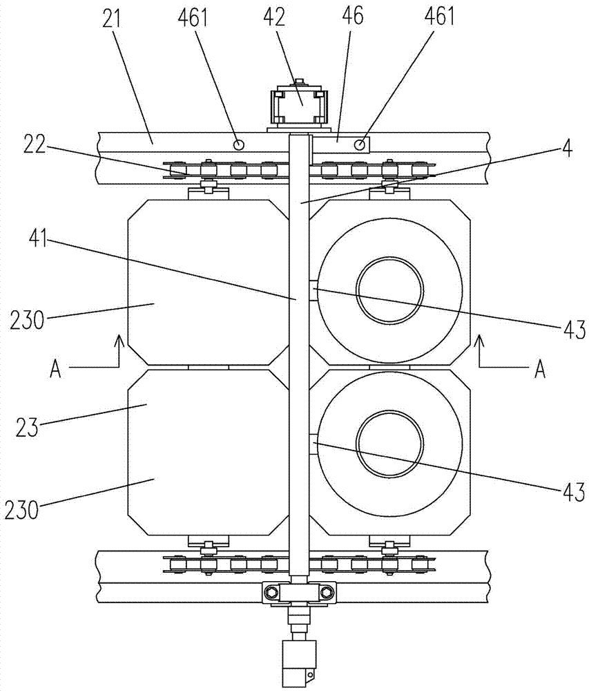
[0029] Such as Figure 1 to Figure 7As shown, a ceramic drying device includes a first transmission mechanism 1, a first drying system 10, a second transmission mechanism 2, a second drying system 20 and a transfer device 3, and the second transmission mechanism 2 is parallel to It is arranged on the side of the first transmission mechanism 1, the first drying system 10 and the second drying system 20 are respectively arranged above the first transmission mechanism 1 and the second transmission mechanism 2, and the transfer device 3 is arranged on the first drying system. On the top of the dry system 10, the second transmission mechanism 2 includes a frame 21 and an annular transmission rail 22 arranged on the frame 21. A number of hanging baskets 23 are evenly erected and distributed on the transmission rail 22, and each hanging basket 23 includes at least A placement unit 230, when the hanging basket 23 includes several placement units 230, several placement units 230 are ar...


PUM


Abstract

A ceramic drying apparatus comprises a first transmission mechanism (1), a first drying system (10), a second transmission mechanism (2), a second drying system (20), and a transferring device (3). The second transmission mechanism (2) is arranged in parallel to and at a side of the first transmission mechanism (1). The first drying system (10) and the second drying system (20) are disposed above the first transmission mechanism (1) and the second transmission mechanism (2), respectively. The second transmission mechanism (2) comprises a machine frame (21) and a ring-shaped transmission track (22) disposed thereabove. A plurality of hanging baskets (23) are evenly set up at the transmission track (22). Each of the hanging baskets (23) comprises at least one disposition unit (230) and located outside the second drying system (20). A first rotating device (4) and a second rotating device (5) are disposed on the machine frame (21) on the second transmission mechanism (2), and both comprise rotating shafts (41) movably disposed at two sides of the machine frame (21) and above the transmission track (22). Rotating arms (43) are fixed to the rotating shafts (41) and horizontally arranged. Suction cup rods (44) are fixed on the rotating arms (43) and vertically arranged. A free end of each of the suction cup rods (44) is provided with a suction cup (45). The ceramic drying apparatus is configured to perform a ceramic drying procedure in steps, in which the first drying system (10) is configured to perform a partially drying process, and bisqueware is rotated by 90°, flipped over by 180°, and then sent to the second drying system (20) to perform a complete drying process. Therefore, the embodiment prevents bisqueware from excessive drying in a mold of the first transmission mechanism (1), uniformly drying the bisqueware, and delivering favorable quality of the bisqueware.

Description

technical field [0001] The invention relates to the field of daily-use ceramic production equipment, in particular to a ceramic drying device. Background technique [0002] Ceramic production includes mud refining, rolling forming, drying, trimming and other technological processes. When working, the mud strip raw materials are first sent to the mud mixer, squeezed by spiral blades and sucked out of the air to form dense mud billets. It is automatically sent into the mold, and after being rolled into the shape of a porcelain billet by a rolling forming device, it enters a drying device for drying, and then the dried porcelain billet is sent to a trimming device for finishing treatment. The existing ceramic rolling forming production line only includes a dryer, and the porcelain blank is transferred to the trimming device after drying once. In this kind of production line, the porcelain blank is not dried uniformly and is easy to deform, which affects the quality of ceramic p...

Claims


Application Information

Patent Timeline
Patent Type & Authority Patents(China)
IPC IPC(8): F26B15/12F26B25/02
CPCF26B15/12F26B25/02
Inventor 陈联社柯国镇胡大宛尹强承忠吴嘉猛朱树兵柯勇
Owner FUJIAN JINJIANG JILONG MACHINE IND
Learn More