Real-time bridge state parameter monitoring and alarm system

A technology of real-time monitoring and state parameters, applied in the field of mechanical measurement, can solve the problems of waste of data resources, difficult to accurately synchronize output data, and inconvenient in all-round intelligent inspection of bridges, so as to ensure comprehensive and reasonable monitoring, easy to grasp and analyze, and save money The effect of data resources

Inactive Publication Date: 2015-12-09
合肥徽拓电子技术有限公司
View PDF5 Cites 18 Cited by
  • Summary
  • Abstract
  • Description
  • Claims
  • Application Information

AI Technical Summary

Problems solved by technology

[0005] (1) There are many types of sensors, and it is difficult to achieve accurate synchronization of various output data, which brings difficulties to the fusion, processing and analysis of subsequent data;
[0006] (2) The monitoring of bridge deformation is long-term. In addition to the large number of sensors, in order to save data resources and reduce the pressure of wireless data transmission and data storage backup, long-term monitoring of static deformation with low time resolution is required. Short-term centralized monitoring with high time resolution, but the existing monitoring system is difficult to achieve the above control, resulting in waste of data resources or difficult to achieve high time resolution measurement of special events;
[0007] (3) Lack of timely transmission of alarm information to the client for manual processing
These defects bring inconvenience to the intelligent all-round inspection of the bridge, and affect the safety, maintenance, management and operation of the bridge.

Method used


Image

  • Real-time bridge state parameter monitoring and alarm system
  • Real-time bridge state parameter monitoring and alarm system
  • Real-time bridge state parameter monitoring and alarm system

Examples


Embodiment Construction

[0031] The technical solution of this patent will be further described in detail below in conjunction with specific embodiments.

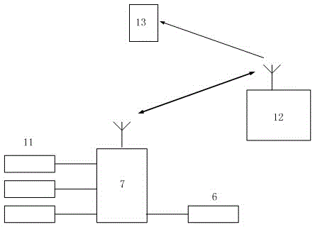
[0032] see figure 1 and figure 2 , the present invention provides a real-time monitoring and alarm system for bridge state parameters, including a bridge detection sensor group 11, a snapshot camera 6, a field master controller 7, a remote service processor 12 and a client terminal 13.

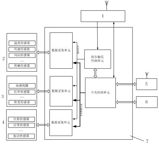
[0033] In the present invention, the bridge detection sensor group 11 includes an environment detection sensor unit 2, a flow detection sensor unit 3 and a structure detection sensor unit 4; wherein, the environment detection sensor unit 2 includes one of a temperature sensor, a wind speed sensor, and a rainfall sensor one or more combinations; the flow detection sensor unit 3 includes one or more combinations of ground sensing sensors, infrared sensors, and load cells; the structure detection sensor unit 4 includes one or more of displacement sensors, strain sen...


PUM


Abstract

The invention discloses a real-time bridge state parameter monitoring and alarm system. The real-time bridge state parameter monitoring and alarm system comprises a bridge detection sensor group, a snapshot camera, a field main controller, a far-end service processor and a client, wherein the bridge detection sensor group comprises an environment detection sensor unit, a flow detection sensor unit and a structure detection sensor unit, and the field main controller comprises a central control unit, and a data acquisition unit, a synchronization triggering control unit, a field wireless data transmission unit and a GPS time service unit which are connected with the central control unit. According to the real-time bridge state parameter monitoring and alarm system, time signals of a GPS are added to measurement results, time indication codes are added to output data of the sensor and the camera, and precise data synchronization is realized; analysis and determination on data of structure detection sensors are carried out to realize complete monitoring on dynamic deformation, data resources are saved, and wireless data transmission and data storage and copy pressure is reduced.

Description

technical field [0001] The invention belongs to the technical field of mechanical measurement and relates to a multi-parameter measurement technology applicable to bridge targets, in particular to a system for real-time measurement and alarm of deformation parameters of bridges. Background technique [0002] The deformation of the bridge mainly includes static deformation and dynamic deformation. Static deformation refers to the deformation that changes slowly such as subsidence, inclination and stress relaxation of the foundation. Dynamic deformation refers to the short-term deformation caused by wind, temperature, earthquake and traffic load. Its parameter monitoring It plays an important role in the security assessment and analysis of the target. Many countries in the world have invested a lot of manpower and material resources in the research of bridge deformation measurement technology. [0003] Traditional bridge deformation detection instruments include dial indicato...

Claims


Application Information

Patent Timeline
Patent Type & Authority Applications(China)
IPC IPC(8): G01B21/32G01B11/16G01C11/00
Inventor 方成和高文武
Owner 合肥徽拓电子技术有限公司
Why Eureka
Try Eureka