Smart grid sensing device

A technology of sensing device and smart grid, applied in the direction of measuring device, measuring electricity, fault location, etc., can solve the problems of low efficiency of troubleshooting and positioning, single method of line selection device, insulation breakdown, etc., to solve single-phase grounding faults Effects of line selection and positioning problems

Inactive Publication Date: 2016-06-15
苏州银蕨电力科技有限公司
View PDF5 Cites 1 Cited by
  • Summary
  • Abstract
  • Description
  • Claims
  • Application Information

AI Technical Summary

Problems solved by technology

[0005] (1) Lack of online measurement data, unable to know the operation status of the line in time;
[0006] (2) The efficiency of troubleshooting and positioning is extremely low, and even artificial power outages are required to find fault lines and fault locations;
[0007] (3) For safety considerations, generally only power far below the rated line capacity is transmitted, resulting in a great waste of the existing distribution network
[0009] (1) Single line selection device method
Generally, it is limited to a certain line selection method such as single-ended electrical quantity ratio amplitude ratio method, fifth harmonic method, energy function method, wavelet method, etc., and the success rate is extremely low;
[0010] (2) Traditional fault indicators are based on local overcurrent, only suitable for single-ended power lines, and battery-powered, short life, easy to break
Its disadvantage is that when a single-phase permanent ground fault occurs, it is difficult to detect which line is faulty
The non-faulty phase voltage will increase significantly due to faults, and intermittent arcing grounding may cause arc overvoltage, which threatens the insulation safety of system equipment. Long-term operation may cause insulation breakdown and malignant phase-to-phase faults. The faulty line must be determined as soon as possible. , troubleshooting, otherwise there will be a big security risk

Method used


Image

  • Smart grid sensing device
  • Smart grid sensing device
  • Smart grid sensing device

Examples


Embodiment Construction

[0040] The present invention will be described in more detail below in conjunction with the accompanying drawings and preferred embodiments.

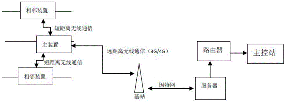
[0041] like figure 1 Shown is a schematic diagram of this embodiment applied to a distribution network. The device of this embodiment is installed on each busbar and branch line of the distribution network of 35KV and below, and 3 devices (phase A, phase B and phase C corresponding to the power line) will be installed at each place, and the global positioning system ( GPS) to realize the precise synchronization of the internal sampling data of each point device, and then collect them on a main device through a short-distance wireless communicator, and then the main device finally forwards it to the Background master control station. The background master control station adopts various fault judgment algorithms and manual decision-making systems to realize the comprehensive line selection and location of faults.

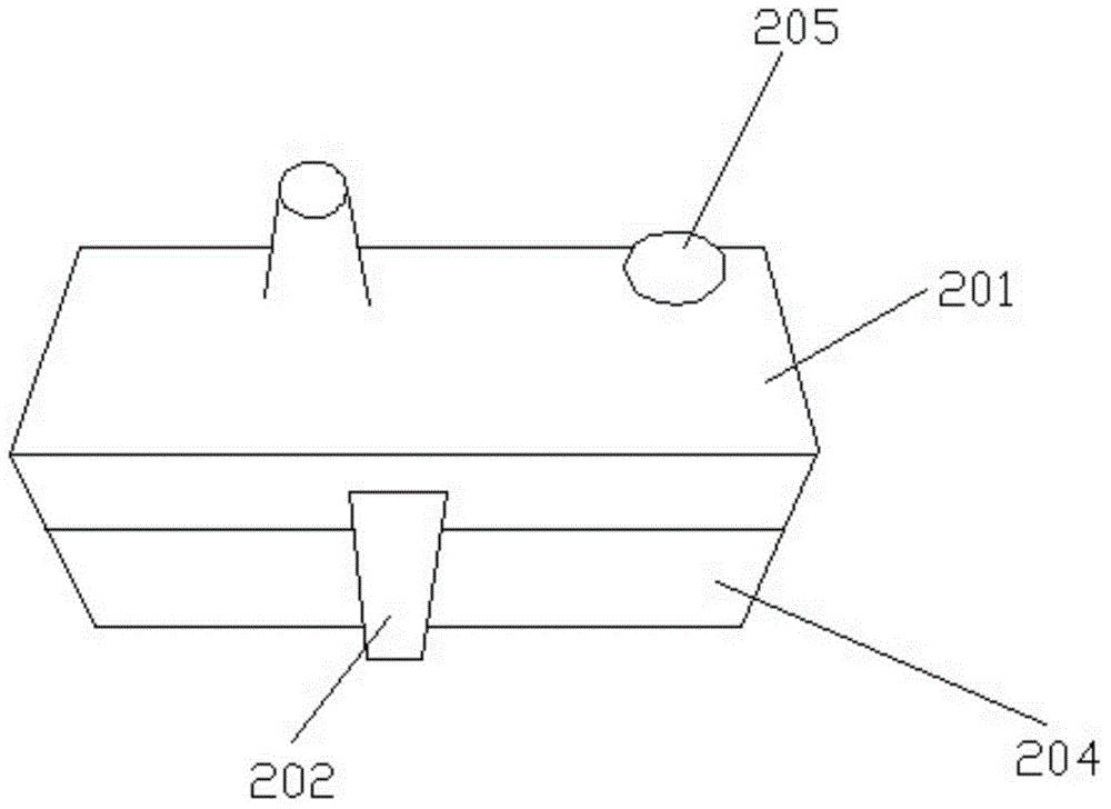
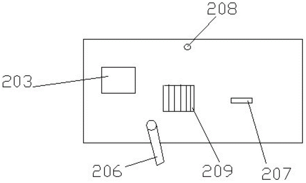
[0042] figure 2 an...


PUM


Abstract

The present invention discloses a smart grid sensing device. The smart grid sensing device comprises a central processing unit, a global positioning system connected with the central processing unit, a large-volume data buffer, a temperature sensor, a high-precision analog-digital converter, an induction taking power circuit, a short-range wireless communication module and a long-range wireless communication module. The central processing unit is connected with a digital analog converter which is connected with a crystal oscillator, and the crystal oscillator is connected with the central processing unit. Through adoption of a mode of taking power from power induction current, the smart grid sensing device supplies power to a device with no need for external power source and battery; and the smart grid sensing device is not limited by single-end power supply and is slightly influenced by the factors such as the fluctuation of load, the harmonic wave, the grounding resistance, the fault close angle and the like; and moreover, the original fault transient state information and the opposite end information are effectively utilized in the fault feature extraction, the single-phase earth fault line selection and positioning problems of a small current grounding system are effectively solved.

Description

technical field [0001] The invention relates to a smart grid sensing device in a power distribution network system below 35kV. Background technique [0002] The State Grid Corporation of China has proposed the development goal of building a strong smart grid in an all-round way. The grid status detection technology provides a strong technical support for improving the security and stability of the smart grid and the efficiency of grid equipment management. [0003] The three goals of the intelligent power distribution system are: safety and reliability, high quality and efficiency, and flexible interaction. The key projects in the power distribution link in the smart grid include: distribution network grid construction and transformation, distribution automation pilot and practical application, association and integration of related information islands, access and control of distributed power sources, and interaction of power distribution systems application etc. In order ...

Claims


Application Information

Patent Timeline
Patent Type & Authority Applications(China)
IPC IPC(8): G01R31/08G01R31/02
Inventor 方明朱志明倪贵成徐兴文
Owner 苏州银蕨电力科技有限公司
Why Eureka
Try Eureka