Design method of moving cam contour line during sine acceleration linear motion of roller center

A technology of sinusoidal acceleration and design methods, applied in calculation, special data processing applications, instruments, etc., can solve problems such as lack of reference methods, difficult design, and unreasonableness of cam contours

Active Publication Date: 2015-12-09
CHANGZHOU UNIV
View PDF3 Cites 4 Cited by
  • Summary
  • Abstract
  • Description
  • Claims
  • Application Information

AI Technical Summary

Problems solved by technology

[0005] In order to overcome the deficiencies of the prior art, the present invention provides an intuitive, fast and convenient design method for the design of the moving cam profile when the center of the roller moves reciprocatingly according to the law of sinusoidal acceleration, so as to solve the current design of this type of moving cam mechanism. Difficulties and unreasonable design caused by the lack of reference methods or manual design based on experience in the design of the convex contour

Method used


Image

  • Design method of moving cam contour line during sine acceleration linear motion of roller center
  • Design method of moving cam contour line during sine acceleration linear motion of roller center
  • Design method of moving cam contour line during sine acceleration linear motion of roller center

Examples


Embodiment Construction

[0033] The implementation process of the method for designing the moving cam profile of the present invention will be described in detail below in conjunction with the accompanying drawings.

[0034] 1) Start the system;

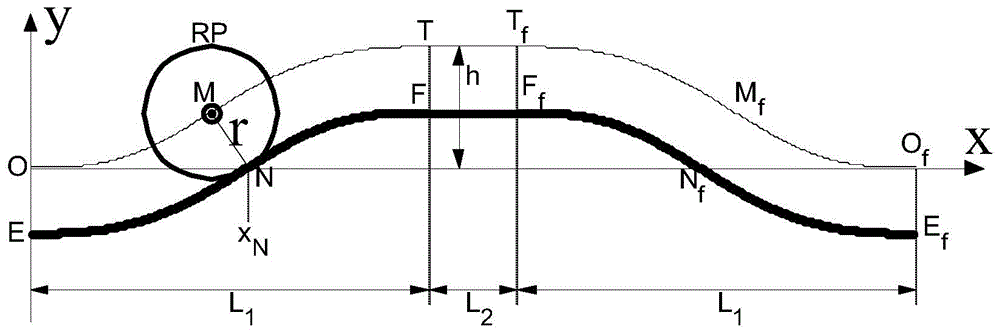
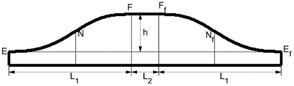
[0035] 2) According to the design conditions or the actual requirements of the production site, formulate the radius r of the roller, the lift h of the roller, the moving speed V of the cam, and the displacement L of the cam corresponding to the lift h of the roller 1 , and the horizontal segment straight line FF f Corresponding cam displacement L 2 ;

[0036] 3) Take the initial rising point of the roller center as the origin O of the coordinate system, the opposite direction of the cam movement is the x direction, and the upward direction perpendicular to the cam movement direction is the y direction. The acceleration equation of the center of the roller in the moving part---moving cam mechanism is a sine function:

[0037] a ...


PUM


Abstract

The invention provides a design method of a moving cam contour line during sine acceleration linear motion of a roller center. The design method aims at overcoming defects that existing design of the moving cam contour line is lack of a reference method, and the design is conducted manually by experience. The cam contour line formed through the design method comprises ascent stage sine curves EN and NF, a horizontal stage line FF<f> and descent stage sine curves F<f>N<f> and N<f>E<f>, and a contour curve of a moving cam is obtained by connecting lines of all the stages. The design method of the moving cam contour line during the sine acceleration linear motion of the roller center has the advantages that the moving cam contour line obtained through the design method is smooth and continuous, the phenomenon of cuspidal points or motion distortion does not occur, when the roller center conducts sine acceleration reciprocating linear motion, saltation of the moving speed of the roller center does not occur, the rigid shock of a cam mechanism is eliminated, vibration and noise of a moving part are reduced, the transmission efficiency of the mechanism is improved, and the service life of the mechanism is prolonged; the design method is visual in process and easy to master, and convenience is provided for performance optimization and numerical control machining of the moving cam mechanism.

Description

technical field [0001] The invention relates to a design method of a cam profile, in particular to a design method of moving a cam profile when the center of a roller performs reciprocating linear motion according to the law of sinusoidal acceleration, and belongs to the technical field of cam mechanism design. Background technique [0002] A cam is a component with a curved profile that can convert one kind of movement into another kind of movement. As long as the contour curve of the cam is properly designed, the follower can obtain any expected movement law, and the mechanism is simple and compact, so the cam Mechanisms are widely used in various machinery, especially in high-speed, high-precision transmission and guiding mechanisms. The contour curve of the cam and the follower together realize the transformation of the motion form. When designing a machine, when the follower must accurately realize a certain expected motion law, the cam mechanism is often used. [0003...

Claims


Application Information

Patent Timeline
Patent Type & Authority Applications(China)
IPC IPC(8): G06F19/00
Inventor 祝海林邹旻
Owner CHANGZHOU UNIV
Why Eureka
Try Eureka