Impeller for fan

A blower and impeller technology, applied in the direction of mechanical equipment, machines/engines, liquid fuel engines, etc., can solve the problems of insufficient lightening effect, insufficient lightening effect, large specificity of thin steel plate, etc., and achieve strength improvement , Product cost reduction, low noise and vibration effects

Inactive Publication Date: 2015-12-09
NISSHINBO MECHATRONICS
View PDF4 Cites 2 Cited by
  • Summary
  • Abstract
  • Description
  • Claims
  • Application Information

AI Technical Summary

Problems solved by technology

[0004] However, in the case of using ordinary aluminum for the blade parts, although there is an effect of reducing weight compared with steel plates, the tensile strength of the material is low, and it is easily deformed by external forces, so there is a problem in reducing the thickness of the blade parts. limit, and did not obtain sufficient lightweight effect
In addition, when thin steel plates with high tensile strength are used for the blade members, sufficient air blowing performance can be obtained by reducing the thickness of the blades, but due to the high specificity of the thin steel plates, no sufficient effect can be obtained in terms of weight reduction.

Method used


Image

  • Impeller for fan
  • Impeller for fan
  • Impeller for fan

Examples


Embodiment 1

[0050] Structure of the impeller of the present invention

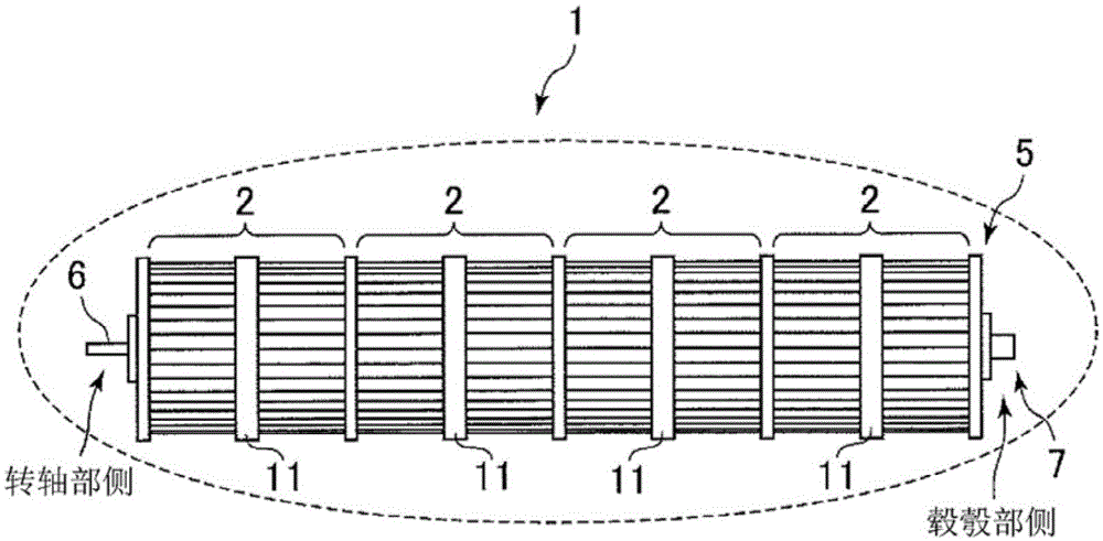
[0051] of the present invention figure 1 The impeller 1 is composed of several figure 2 The constituent unit 2 of the impeller, the disc-shaped fixed plate 5 at the hub hub side, the rotating shaft part 6 and the hub hub part 7 constitute. The rotating shaft portion 6 is attached to the disk-shaped member 3 of the constituent unit 2 at one end portion of the impeller 1 . The hub-side disk-shaped fixing plate 5 is attached to the blade member side of the constituent unit at the other end of the impeller 1 . The hub portion 7 is provided on the hub-side disk-shaped fixing plate 5 .

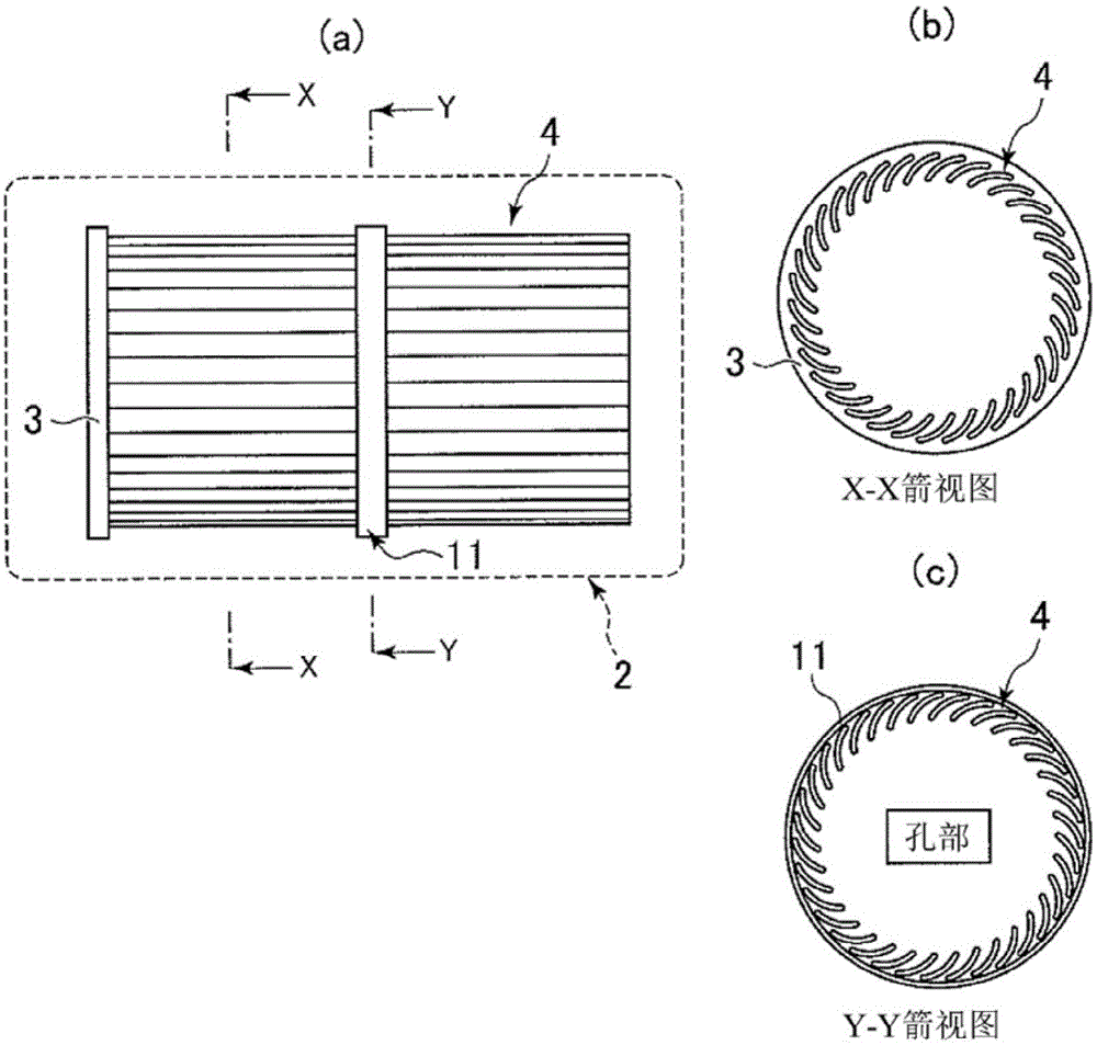
[0052] Structure of blade member (constituent unit 2)

[0053]The constituent unit 2 of the impeller 1 is composed of a disk-shaped member 3 , blade members 4 and a reinforcing ring 11 . As the material, synthetic resins such as AS resin, ABS resin, PS resin, and PP resin can be used. The resins described here are just examples, an...

Embodiment

[0059] In this embodiment, the constituent unit 2 and the hub-side disk-shaped fixing plate 5 are manufactured using AS resin material which is a synthetic resin. The blade parts that make up the unit are figure 2 In the form shown, the average thickness was 0.4 mm, the length was 160 mm, and the number of sheets was 35. In addition, the diameter of the constituent unit was set to 106 mm at the outermost portion of the blade member 4 . In addition, a reinforcement ring 11 is integrally formed at a substantially central portion in the longitudinal direction of the blade member constituting the unit (the center position of the blade member with a length of 160 mm). Such a constituent unit is integrally molded from the raw material of the above-mentioned material by injection molding. In addition, by ultrasonic fusion, four such constituent units and the hub-side disk-shaped fixing plate 5 made of the same material as the constituent units are bonded to produce figure 1 The i...

Embodiment 2

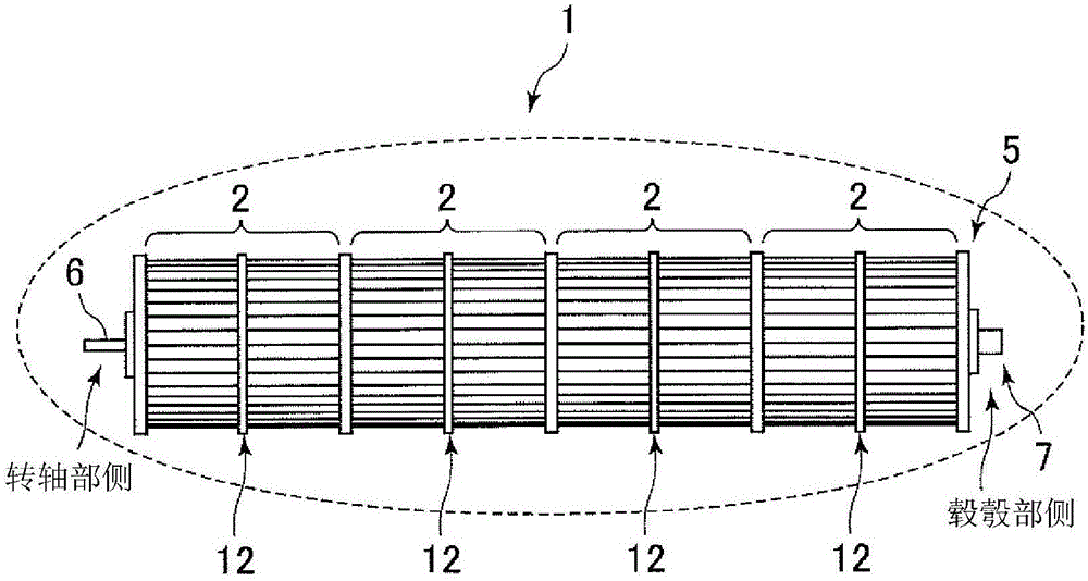
[0073] This example is made by changing the material of Example 1 in the following manner, and other conditions are set to be the same. Therefore, the shape of the impeller of this embodiment and the shape of its constituent units are consistent with figure 1 and figure 2 same.

[0074] The materials of the constituent units 2 of the impeller 1 and the hub-side disc-shaped fixing plate 5 will be described. As the material, a composite material of AS resin and glass fiber, a composite material of ABS resin and glass fiber, a composite material of PS resin and glass fiber, or a composite material of PP resin and glass fiber can be used. In this case, the glass fiber content is preferably 10% to 40% by weight of the whole, and more preferably 10% to 30% of the whole. If the content of the glass fiber exceeds 40% by weight of the whole, there is a possibility that the blade parts constituting the unit may be defectively formed. In addition, if the glass fiber content is less ...


PUM

PropertyMeasurementUnit
thicknessaaaaaaaaaa
lengthaaaaaaaaaa
diameteraaaaaaaaaa

Abstract

The objective of the present invention is to provide an impeller that is much lighter in weight, has improved blowing performance, and has a simpler manufacturing process, by using a resin material or the like. This impeller is formed by securing multiple blade members in a cylindrical manner to multiple disk-shaped securing plates. A synthetic resin material is used for the blade members of the impeller, and average thickness of the blade members of the impeller ranges from 0.3-1.2 mm. The configuration is such that a ring-shaped member or a plate-shaped member, which is formed integrally with each blade member, is provided at a location in the direction of elongation of the blade members formed in a cylindrical manner.

Description

technical field [0001] The present invention relates to an impeller used in a blower such as a fluid blower. Background technique [0002] Due to environmental issues and resource conservation efforts in recent years, as well as improvements in the performance of blowers, there have been increasing demands for reducing the weight of the impeller and achieving low noise and low vibration of the impeller. [0003] The impeller of the conventional air blower realizes the improvement of air supply performance and weight reduction by reducing the thickness of the blade parts. In addition, in order to achieve high rigidity and high heat resistance, ordinary aluminum materials, plastics containing glass fibers, or high-resistant plastics have been used. Tensile strength steel plate is used as the material of the blade parts. [0004] However, in the case of using ordinary aluminum for the blade parts, although there is an effect of reducing weight compared with steel plates, the t...

Claims


Application Information

Patent Timeline
Patent Type & Authority Applications(China)
IPC IPC(8): F04D17/04F04D29/02
CPCF04D17/04F04D29/023F04D29/283F05D2300/44F05D2300/603
Inventor 渡辺仁堀収志
Owner NISSHINBO MECHATRONICS
Why Eureka
Try Eureka