
Special mobile plant wall system for building external wall

A technology for building exterior walls and plants, which is applied in the field of mobile plant wall systems, can solve the problems that the green belt and the central green space are far away from the residents' residences, it is difficult to directly improve and adjust the indoor microclimate, and the green belt occupies a small area, etc., to achieve improvement. Effect of indoor microclimate and air quality, light weight and high usability

Active Publication Date: 2015-12-16
HARBIN INST OF TECH
View PDF8 Cites 4 Cited by
  • Summary
  • Abstract
  • Description
  • Claims
  • Application Information

AI Technical Summary

Problems solved by technology

[0003] The purpose of the present invention is to provide a mobile plant wall system dedicated to building exterior walls to solve the problem that the green belts in urban buildings occupy a small area due to limited space, resulting in increasingly serious urban heat island phenomenon and urban air pollution. At the same time, there is also the problem that the green belt and the central green space are far away from the residents' residences, so it is difficult to directly improve and adjust the indoor microclimate

Method used


Image

  • Special mobile plant wall system for building external wall
  • Special mobile plant wall system for building external wall
  • Special mobile plant wall system for building external wall

Examples


specific Embodiment approach 1

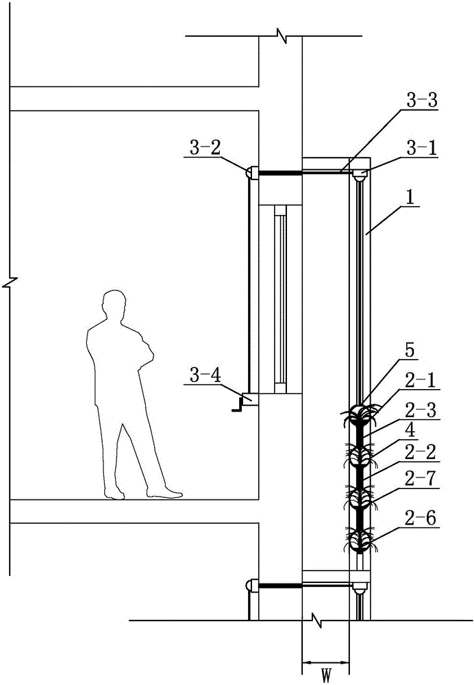
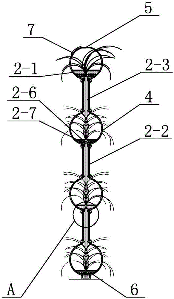
[0016] Specific implementation mode one: combine figure 1 , figure 2 , image 3 and Figure 4 Describe this embodiment, which includes a fixed frame 1, a plant planting wall assembly and a plurality of guide devices 3, the fixed frame 1 is fixedly connected to the exterior wall of the building, and the plant planting wall assembly is arranged in the fixed frame 1 And slidingly fit with the fixed frame 1, a plurality of guide devices 3 are arranged side by side on the outer wall of the fixed frame 1, and the plant planting wall assembly is connected with the indoor wall through a plurality of guide devices 3;

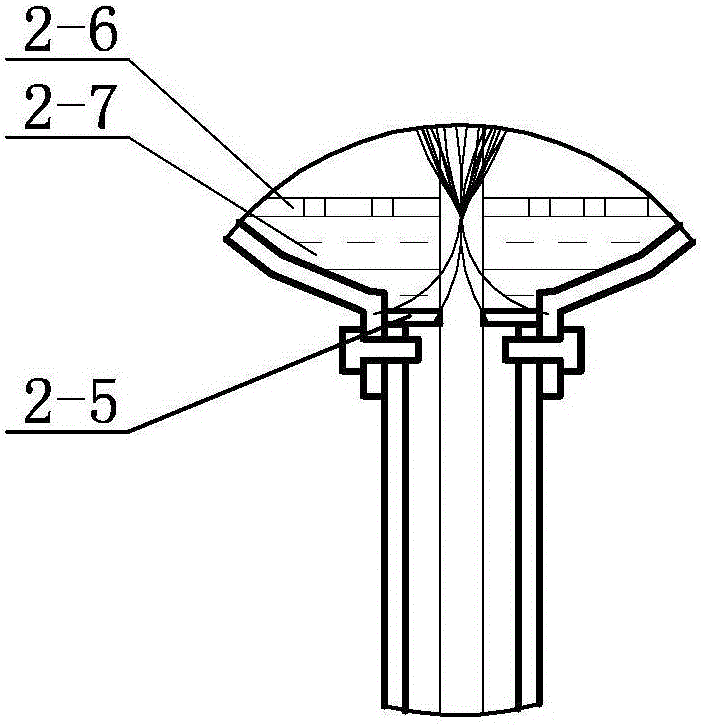
[0017] The plant planting wall assembly includes a plurality of circular tubes 2-1, N sets of connecting vertical tubes 2-2 and multiple percolation tubes 2-3, and the multiple circular tubes 2-1 are arranged side by side from top to bottom On the inner wall of the fixed frame 1, the two ends of each circular tube body 2-1 are arranged on the inner wall of the fixed ...

specific Embodiment approach 2

[0027] Specific implementation mode two: combination figure 1 and figure 2 Describe this embodiment. In this embodiment, the distance from the inner side of each circular tube body 2-1 to the outer wall of the building is W, and the value range of W is 10-20 cm. The limitation of W is conducive to the smooth movement of the box body. If necessary, the thickness of the plants at the inner side of the box body can be controlled by trimming the plant wall, and when the plant wall is raised to cover the window, the box body, top plate, and side plate of the plant can be covered. And the bottom plate forms a nearly closed space. Other unmentioned components and connections are the same as those in the first embodiment.

specific Embodiment approach 3

[0028] Specific implementation mode three: combination figure 1 and figure 2 To illustrate this embodiment, in this embodiment, a plurality of permeation holes are evenly processed on the pipe wall of each percolation pipe body 2-3. The permeation velocity of each permeation hole is 0.2-2.0 m / s. Other unmentioned components and connections are the same as those in the second embodiment.


PUM


Abstract

The invention discloses a special mobile plant wall system for a building external wall and relates to a mobile plant wall system. The system is to solve the problem that green lands and open spaces in urban building groups are small in area as a result of limited space to lead to increasing seriousness of urban heat island effect and urban air pollution and the indoor micro-climate cannot be directly improved and adjusted as green belts and central green lands are relatively far from residence. A plurality of connecting pipes in each group of connecting pipes are vertically and coaxially arranged, each connecting pipe is communicated between every two adjacent round pipe bodies, each infiltration pipe body sequentially passes through the plurality of round pipe bodies and the plurality of connecting pipes which are alternately arranged from top to bottom, a plurality of plant growing holes are formed on the wall of each round pipe body, the uppermost round pipe body is the first round pipe body, the lowermost round pipe body is the end round pipe body, a rainwater collecting opening is formed in the top of the first round pipe body, and a rainwater drain outlet is formed in the bottom of the end round pipe body. The system provided by the invention is used for building groups.

Description

technical field [0001] The invention specifically relates to a mobile plant wall system dedicated to building exterior walls. Background technique [0002] The urban heat island effect refers to the "heating" of the city due to factors such as a large amount of artificial heat generation, high heat storage bodies such as buildings and roads, and the reduction of green spaces. The temperature in the city is significantly higher than that in the outer suburbs. On the near-surface temperature map, the suburban temperature changes little, while the urban area is a high-temperature area, like an island protruding from the sea. Since this type of island represents a high-temperature urban area, it is vividly called an urban heat island. Due to the limited space in urban buildings, the green belt occupies a small area or cannot be expanded, resulting in the urban heat island phenomenon and urban air pollution becoming more and more serious. The beneficiaries, especially the elder...

Claims


Application Information

Patent Timeline
Patent Type & Authority Applications(China)
IPC IPC(8): A01G31/06E03B3/02
CPCA01G31/06E03B3/02Y02A20/108Y02A30/60Y02P60/21
Inventor 薛滨夏李同予魏利李航程一红
Owner HARBIN INST OF TECH
Learn More