Tea drying machine

A technology of tea dryer and drying box

Inactive Publication Date: 2015-12-16
ANHUI KUDZUVINE ROOT PRODUCTIVITY PROMOTION CENT CO LTD
View PDF3 Cites 7 Cited by
  • Summary
  • Abstract
  • Description
  • Claims
  • Application Information

AI Technical Summary

Problems solved by technology

[0002] The hot air flow provided by the heating device of the existing tea dryer to the drying chamber is straight and cannot rotate in the drying chamber, and the flow direction of the air flow will be hindered

Method used


Image

  • Tea drying machine

Examples


Embodiment 1

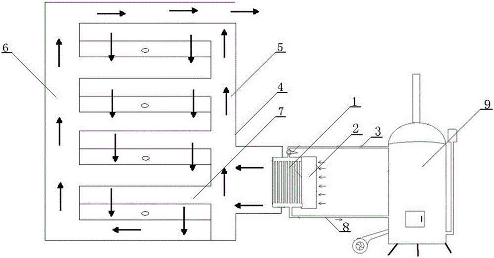
[0017] Such as figure 1 As shown, the tea drying machine of the present invention includes a drying box 4 , a drying chamber 7 arranged in the drying box 4 and a heating device connected to the drying box 4 .

[0018] The right side of the drying box 4 is provided with a vertical hot air channel 5, the left side of the drying box 4 is provided with a vertical air outlet channel 6, and a plurality of drying chambers 7 are vertically distributed in the drying box 4. , the hot air passage 5 and the air outlet passage 6 are connected through the drying chamber. There are 3 drying chambers, placed side by side and vertically, and the different drying chambers are connected in parallel. There is an inlet on the right side of the drying chamber 7, which is directly connected to the hot air passage 5, the lower end of the drying chamber 7 has an outlet, and the outlet directly communicates with the air outlet channel 6.

[0019] The heat supply device includes a boiler 9, a heat exch...

Embodiment 2

[0024] The difference between embodiment 2 and embodiment 1 is that there are 8 drying chambers in embodiment 2, which are connected in parallel. In order to meet the heat requirements of more drying chambers, oil is used as the medium for heating.

[0025] The application method of the present invention is:

[0026] Before starting work, add medium in the boiler 9, the added medium is at least 50 centimeters higher than the high-temperature liquid delivery pipe 8. Then start heating, and at the same time turn on the pump. Under the action of the pump, the medium enters the high-temperature liquid delivery pipe 8, then enters the heat exchanger 1, then enters the low-temperature liquid return pipe 3 and finally returns to the boiler 9. When the liquid enters the heat exchanger 1 , due to the action of the electric fan, the cold air is heated and enters the hot air channel 5 , passes through the drying chamber in parallel and finally returns to the outside through the air outl...


PUM


Abstract

The invention discloses a tea drying machine which comprises a drying box, drying chambers arranged in the drying box, and a heating device connected with the drying boxes, wherein a vertical hot air channel is arranged on the right side of the drying box, and a vertical air discharging channel is arranged on the left side of the drying box; a plurality of drying chambers are vertically distributed in the drying box; inlets communicated with the hot air channel are formed in the right sides of the drying chambers; outlets communicated with the air discharging channel are formed in the lower ends of the drying chambers; the heating device comprises a boiler and a heat exchanger; the heat exchanger is connected with the boiler through a high-temperature liquid conveying pipe and a low-temperature liquid backflow pipe; the heat exchanger comprises a heat dissipation pipe and a fan; the heat exchanger is connected with the hot air channel. Therefore, tea can be fully and uniformly dried, and cannot be polluted.

Description

technical field [0001] The invention relates to a tea production equipment, in particular to a tea drying machine. Background technique [0002] The hot air flow provided by the heat supply device of the existing tea dryer to the drying chamber is straight, and cannot rotate in the drying chamber, and the flow direction of the air flow will be hindered, resulting in insufficient and uneven drying. The existing tea dryers also use charcoal heating because the heating equipment is too close to the drying chamber, and the heating equipment may pollute the tea leaves. Contents of the invention [0003] The technical problem to be solved by the present invention is to provide a tea drying machine, so that the tea can be fully and evenly dried without being polluted. [0004] To achieve the above object, the present invention provides a tea dryer, which includes a drying box, a drying chamber arranged in the drying box, and a heating device connected with the drying box. The r...

Claims


Application Information

Patent Timeline
IPC IPC(8): A23F3/06
Inventor 不公告发明人
Owner ANHUI KUDZUVINE ROOT PRODUCTIVITY PROMOTION CENT CO LTD
Why Eureka
Try Eureka