Circuit structure of milk foaming machine

A circuit structure and technology of milk pump, applied in electrical components, DC motor speed/torque control, control system, etc., can solve the problems of high price and cost, bulky transformer structure, complicated circuit structure, etc., and achieve the effect of simplifying the structure

Inactive Publication Date: 2015-12-16
谢玉翠
View PDF0 Cites 1 Cited by
  • Summary
  • Abstract
  • Description
  • Claims
  • Application Information

AI Technical Summary

Problems solved by technology

At present, there are two types of circuits for milk frothers on the market: 1. The alternating current outputs constant voltage direct current to the motor through the switching power supply. Due to the characteristics of the switching power supply itself, this kind of circuit structure is complicated and the price is high; 2. The alternating current passes through the transformer. and rectification circuit to supply power to the motor, the overall weight of the milk frother increases due to the bulky structure of the transformer

Method used


Image

  • Circuit structure of milk foaming machine

Examples


Embodiment Construction

[0012] The application will be further described below in conjunction with the accompanying drawings of the description.

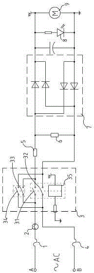
[0013] Such as figure 1 As shown, a circuit structure of a milk frother includes a heating plate power supply circuit, a motor power supply circuit and a relay self-locking circuit 3. The heating plate power supply circuit realizes the heating function of the heating plate, and the motor power supply circuit realizes the motor stirring function.

[0014] The power supply circuit of the heating plate is powered by the AC terminal A through the thermal fuse 1, the temperature controller 2, the first micro switch 31, the heating plate 5, the step-down resistor 6, the second micro switch 32, and the thermal fuse 4, and then returns to the circuit. To the other end B of the alternating current is formed.

[0015] The electric power supply circuit of the motor passes through the thermal fuse 1, the temperature controller 2, the first micro switch 31, the heatin...


PUM


Abstract

The invention discloses a circuit structure of a milk foaming machine; the circuit structure comprises a heating plate power supply circuit, a motor power supply circuit and a relay self-locking circuit, wherein the heating plate power supply circuit is formed as current at one end A of alternating current sequentially passes through a heating plate and a dropping resistor and then returns to the other end B of the alternating current; and the motor power supply circuit is formed as current at one end A of alternating current sequentially passes through the heating plate, a rectifying circuit and a motor and then returns to the other end B of the alternating current. The alternating current can supply power to the heating plate by virtue of the heating plate power supply circuit, so that a heating function of the milk foaming machine is achieved; in the motor power supply circuit, in order to achieve a purpose of supplying power from the motor after voltage dropping, the motor power supply circuit is integrated with some electronic components in the heating plate power supply circuit, including the heating plate and the relay self-locking circuit, and the alternating current is supplied to the motor after passing through the heating plate, so that the purpose of voltage dropping in the circuit is achieved as the heating plate bears some voltage in the motor power supply circuit; therefore, the structure of the entire circuit of the milk foaming machine is greatly simplified.

Description

technical field [0001] This application relates to a milk frother, especially the control circuit part of the milk frother. Background technique [0002] The current milk frother generally includes a heating function and a stirring function. The heating function is realized by a heating plate, and the stirring function is realized by a motor drive. In addition, in order to achieve the above two functions of the milk frother, the milk frother circuit is generally a step-down rectifier circuit. At present, there are two types of circuits for milk frothers on the market: 1. The alternating current outputs constant voltage direct current to the motor through the switching power supply. Due to the characteristics of the switching power supply itself, this kind of circuit structure is complicated and the price is high; 2. The alternating current passes through the transformer. And the rectification circuit supplies power to the motor. Due to the bulky structure of the transformer,...

Claims


Application Information

Patent Timeline
Patent Type & Authority Applications(China)
IPC IPC(8): A47J43/07H02P7/00
Inventor 谢玉翠
Owner 谢玉翠
Why Eureka
Try Eureka