
A driving wheel anti-slip device of a double-line steel bar hoop bending machine

A technology of anti-skid device and driving wheel, which is applied in the field of steel bar processing equipment, can solve the problems that integral pressure wheels cannot be adapted at the same time, cannot solve the problem of slippage, and support bearing damage, etc., and achieves simple structure, low processing cost and convenient maintenance. Effect

Active Publication Date: 2017-06-20
韶关市华研机械有限公司
View PDF6 Cites 0 Cited by
  • Summary
  • Abstract
  • Description
  • Claims
  • Application Information

AI Technical Summary

Problems solved by technology

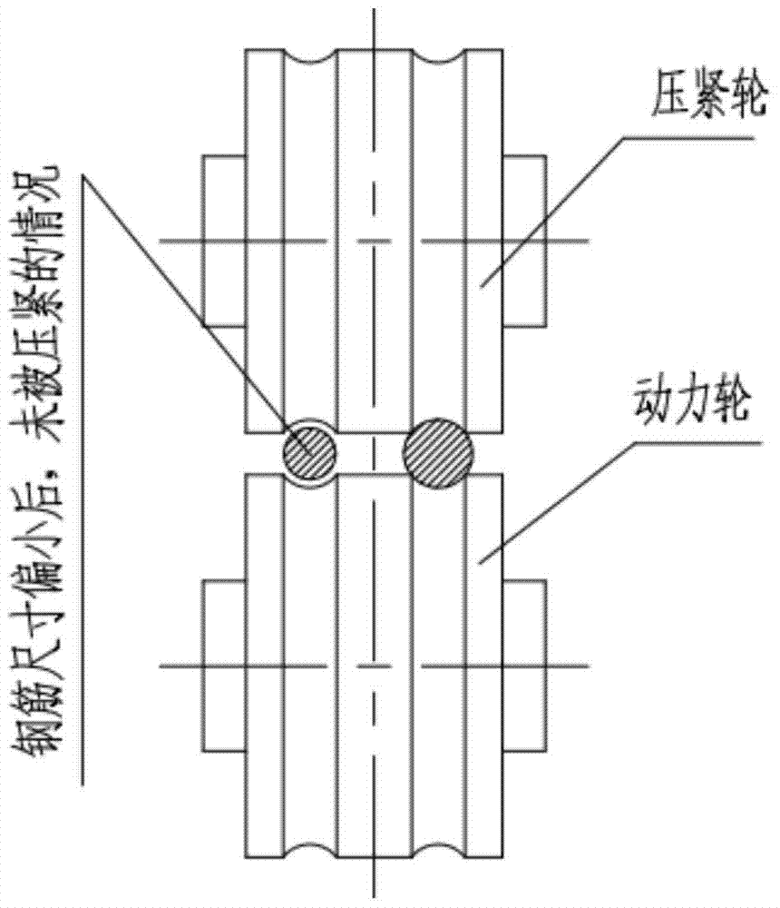
Some companies increase the compression force of the compression wheel to prevent slipping between the steel bar and the power wheel. This measure can indeed reduce the slipping phenomenon, but the essence of this measure is to use the compression wheel to apply a large force to the steel bar to If the size of the two steel bars with size deviation is consistent, this measure itself will cause the steel bars to be obviously flattened and crushed. At the same time, excessive pressing force will cause the support bearings of the pressing wheel and the power wheel premature damage
The integral compression wheel cannot adapt to the size change of two steel bars at the same time, which is the most essential reason why the integral compression wheel can hardly solve the slipping phenomenon during double-wire processing

Method used


Image

  • A driving wheel anti-slip device of a double-line steel bar hoop bending machine
  • A driving wheel anti-slip device of a double-line steel bar hoop bending machine
  • A driving wheel anti-slip device of a double-line steel bar hoop bending machine

Examples


Embodiment 1

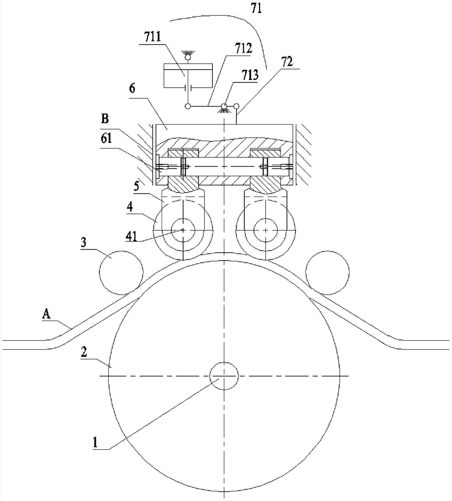
[0021] see image 3 and Figure 4 , the anti-skid device for the driving wheel of the double-line steel bar hoop bending machine of the present invention includes the driving wheel 2 driven by the driving main shaft 1, the straightening wheels 3 arranged on both sides of the driving wheel 2, and at least two wheels arranged on both sides of the center line of the driving wheel 2. A pinch wheel 4, this pinch wheel 4 is an integral type, can press down two reinforcing bars A simultaneously, and the integral pinch wheel 4 adopts flat wheel structure. The pinch wheel 4 is easy to wear and tear due to direct contact with the steel bar A, and should be made of high-strength wear-resistant material and surface hardened. Further, it also includes a pressing wheel seat 5 whose lower end is connected to the axis 41 of the pressing wheel 4, and the upper part of the pressing wheel seat 5 is arranged in the machine base, and its two sides are in clearance fit with the machine base B.

...

Embodiment 2

[0029] see Figure 5 and Figure 6 , the second embodiment is roughly the same as the anti-skid device for the driving wheel of the double wire hoop bending machine of the first embodiment, the only difference is that the main pressing device 71 is a hydraulic cylinder, and the output shaft of the piston of the hydraulic cylinder is movably connected to the connecting rod 62A. The output force of the hydraulic cylinder is relatively large, which can directly provide downforce for the pressing wheel 4A.


PUM


Abstract

The invention discloses an anti-skid device for a driving wheel of a double-line steel bar hoop bending machine, which comprises a driving wheel driven by a driving spindle, straightening wheels arranged on both sides of the driving wheel, and at least two pressing wheels arranged on both sides of the center line of the driving wheel. wheel, the lower end of which is connected to the pressing wheel seat of the pressing wheel axle. The top of the pressing wheel seat is arc-shaped, and is movably installed with the connecting plate in the machine base, and also includes a depressing device, and the depressing device is connected with the connecting plate. The present invention adopts the pressing structure of the swingable integral pressing wheel, which can reliably ensure that the pressing wheel automatically follows the change of the size of the steel bar during the process of steel bar processing, and the surface of the processed stirrup is smooth without crush marks and scratches. traces, and improve the quality of mechanized processing steel bars; the invention has the advantages of simple structure, convenient maintenance, stable work, energy saving and low processing cost.

Description

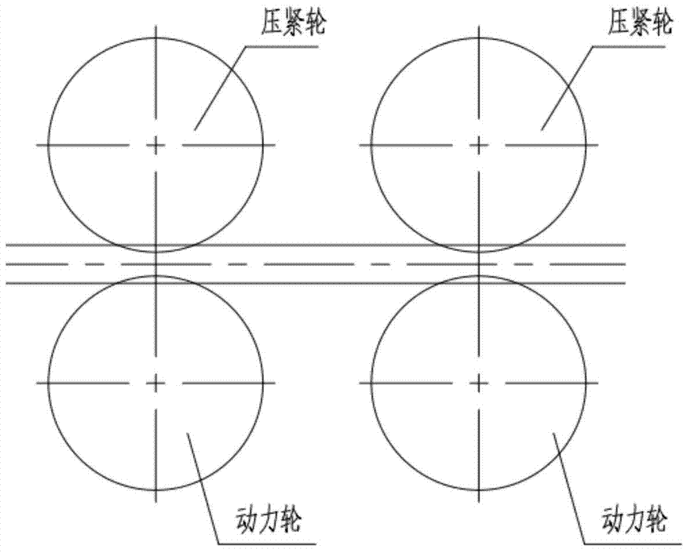
technical field [0001] The invention relates to steel bar processing equipment, in particular to an anti-slip device for driving wheels of a double-line steel bar hoop bending machine. Background technique [0002] When the existing two-wire steel bar bending machine on the market drives the steel bar, it relies on two (or more) integral compression wheels to compress the steel bar on the power wheel, and relies on the friction between the steel bar and the power wheel to feed. The principle is as figure 1 shown. When the compression wheel of the overall structure processes the steel bar, it is very easy to slip between the steel bar and the driving wheel. Slipping will scratch the steel bar and the driving wheel, resulting in premature damage to the pressure wheel and the driving wheel; at the same time, because the steel bar is not synchronized when advancing, the size deviation is large, and the scrap rate of the processed stirrup is high. The economic benefit is low. ...

Claims


Application Information

Patent Timeline
Patent Type & Authority Patents(China)
IPC IPC(8): B21F1/00B21F23/00
Inventor 余尧王力
Owner 韶关市华研机械有限公司
Learn More