Device and method for cutting angle iron

A technology of cutting equipment and cutting method, which is applied in the direction of welding equipment, metal processing equipment, gas flame welding equipment, etc., can solve the problems of cumbersome procedures, low processing efficiency, waste of materials, etc., and achieve simplified processing procedures, improved processing efficiency, and guaranteed The effect of cutting safety

Active Publication Date: 2015-12-16
DUOWEI UNION GRP
View PDF7 Cites 4 Cited by
  • Summary
  • Abstract
  • Description
  • Claims
  • Application Information

AI Technical Summary

Problems solved by technology

[0005] The technical problem to be solved by the present invention is to provide a kind of angle steel cutting equipment and method, which solves the problems that the steel processing method and equipment at the present stage have relatively cumbersome procedures resulting in low processing efficiency, and the waste of materials caused by multiple cutting of steel.

Method used


Image

  • Device and method for cutting angle iron
  • Device and method for cutting angle iron
  • Device and method for cutting angle iron

Examples


Embodiment 1

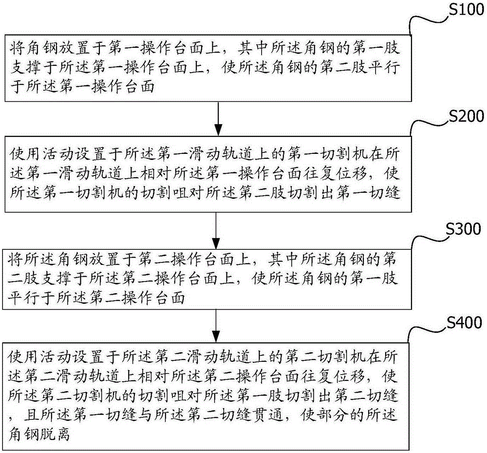
[0045] figure 1 It is a schematic flow chart of an angle steel cutting method provided by the present invention.

[0046] Please refer to figure 1 As shown, the angle steel cutting method provided by the first embodiment of the present invention includes:

[0047] S100: placing the angle steel on the first operating table, wherein the first leg of the angle steel is supported on the first operating table, so that the second leg of the angle steel is parallel to the first operating table;

[0048] S200: Use the first cutting machine movably arranged on the first sliding track to move back and forth on the first sliding track relative to the first operating platform, so that the cutting nozzle of the first cutting machine Cut the first slit in the two limbs;

[0049] S300: Place the angle steel on a second operating table, wherein the second leg of the angle steel is supported on the second operating table, so that the first leg of the angle steel is parallel to the second op...

Embodiment 2

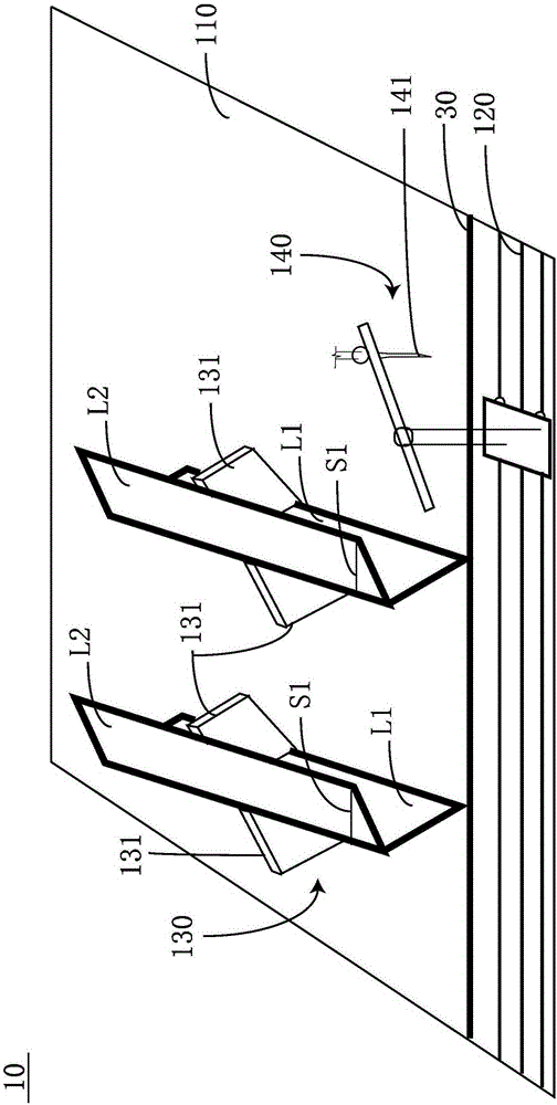
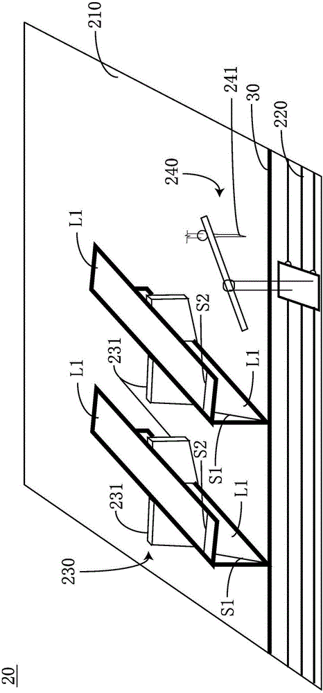
[0060] figure 2 , 3 It is a structural schematic diagram of an angle steel cutting equipment provided by the present invention.

[0061] Please refer to figure 2 , 3 , an angle steel cutting equipment disclosed in the present invention, the angle steel is commonly known as angle iron, which is a long strip of steel whose two sides are perpendicular to each other and form an angle. There are equilateral angle steel and unequal angle steel. The so-called equilateral angle steel means that the two side widths are equal, and the so-called unequal side angle steel means that the two side widths are not equal. The present invention does not make too many limitations, that is, the equipment of the present invention is suitable for both equilateral angle steel and unequal angle steel. It should be pointed out that the sides of the angle steel can also be called limbs, that is, each angle steel has two limbs, which are distinguished by the first limb L1 and the second limb L2 in ...


PUM


Abstract

The invention discloses a device and method for cutting angle iron. The device comprises a first cutting unit and a second cutting unit. The first cutting unit comprises a first operation tabletop, a first sliding rail, a limiting mechanism and a first cutting machine. The first cutting machine is movably arranged on the first sliding rail and moves in a reciprocating manner on the first sliding rail relative to the first operation table. The first cutting machine comprises a first cutting nozzle arranged on the first operation tabletop in a suspended manner, moves in a reciprocating manner along the first cutting machine and is used for cutting a first kerf on a second limb of the angle iron. The second cutting unit comprises a second operation tabletop, a second sliding rail, a positioning mechanism and a second cutting machine. The second cutting machine is used for cutting a second kerf on a first limb of the angle iron. The first kerf is communicated with the second kerf so that part of the angle iron can be disengaged. According to the device and method for cutting the angle iron, the problems that for steel machining in the current stage, processes are complex, so that the machining efficiency is low, and materials are wasted due to multiple times of cutting of steel are solved.

Description

technical field [0001] The invention relates to the field of building material processing, in particular to an angle steel cutting equipment and method. Background technique [0002] In the field of modern architecture, frame structure buildings occupy a relatively large proportion because of their high overall strength and fast construction speed, but they largely rely on the use of construction steel materials, such as angle steel, I-beam, etc. These steel products generally have certain specifications when they leave the factory, and these specifications are generally uniform. When used on construction sites, due to the different lengths and sizes of the required places or different specific shapes, they often need to be reprocessed, such as cutting and chamfering. , stitching, etc. [0003] For example, when the length of the required place is greater than the length of one steel, two or more steels need to be spliced ​​at this time, and splicing generally requires obli...

Claims


Application Information

Patent Timeline
Patent Type & Authority Applications(China)
IPC IPC(8): B23K7/00B23K7/10
CPCB23K7/00B23K7/10
Inventor 吴会超
Owner DUOWEI UNION GRP
Why Eureka
Try Eureka