Chain transmission type automatic film sticking machine and film sticking process thereof

A chain transmission mechanism and chain transmission technology, applied in packaging and other directions, can solve the problems of increased film lamination cost, uneven film lamination, and large product size, and achieve the effects of reducing production costs, improving lamination quality, and improving efficiency

Active Publication Date: 2015-12-16
HOWWEIH ELECTRONIC TECH (HUIZHOU) CO LTD
View PDF5 Cites 8 Cited by
  • Summary
  • Abstract
  • Description
  • Claims
  • Application Information

AI Technical Summary

Problems solved by technology

[0003] Due to the thin thickness of the protective film and the large size of the product, the protective film is easily deformed by manual applicati

Method used


Image

  • Chain transmission type automatic film sticking machine and film sticking process thereof
  • Chain transmission type automatic film sticking machine and film sticking process thereof
  • Chain transmission type automatic film sticking machine and film sticking process thereof

Examples


Embodiment Construction

[0022] In order to describe the technical solution of the present invention in more detail, it is further described in conjunction with the accompanying drawings as follows:

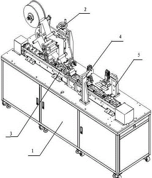
[0023] Such as figure 1 As shown, a chain-driven automatic film lamination machine according to the present invention includes five parts: a support frame 1, a protective film clamping mechanism 2, a chain transmission mechanism 3, a front and rear side film lamination mechanism 4, and a left and right side film laminating structure 5. The chain transmission mechanism 3 is installed on the support frame 1, the protective film clamping mechanism 2 is installed on the support frame 1 and is located on the side of the chain transmission mechanism 3, the front and rear side film sticking mechanism 4 and the left and right side film covering structures 5 Installed on the support frame 1 and located on both sides of the chain transmission mechanism 3 respectively.

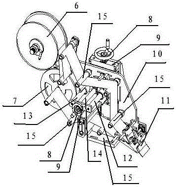
[0024] The main function of the protective ...


PUM


Abstract

A chain transmission type film sticking machine comprises a support, a protective film clamping mechanism, a chain transmission mechanism, a front side face and rear side face film sticking mechanism and a left side face and right side face film sticking mechanism; the chain transmission mechanism is installed on the support; the protective film clamping mechanism is installed on the support and located on the side face of the chain transmission mechanisms; the front side face and rear side face film sticking mechanism and the left side face and right side face film sticking mechanism are installed on the support and located at the two sides of the chain transmission mechanism respectively. According to the technical scheme, the chain transmission type film sticking machine has the beneficial effects that a hinge type conveying belt is adopted to drive all working stations, and an assembly line type film sticking process is achieved; compared with the prior art, manual surface film sticking operation with the efficiency being 100 products per hour is changed into mechanical surface film sticking operation with the efficiency being 400 products per hour, the efficiency is greatly improved, the production cost is reduced, and meanwhile the film sticking quality is improved.

Description

technical field [0001] The invention relates to the field of precision machinery, in particular to a chain-driven automatic film laminating machine. Background technique [0002] After the jig is prepared, it is usually necessary to stick a protective film on the jig to protect it. The existing method is to cover the film manually. When manually coating the product surface, the protective film needs to be torn off and placed on the jig, and then the product is put into the jig, pressed and adsorbed, and then manually corrected. [0003] Due to the thin thickness of the protective film and the large size of the product, the protective film is easily deformed by manual application, which leads to uneven application of the film and high rework rate of defective products. This also led to a substantial increase in the cost of the film. Contents of the invention [0004] Aiming at the deficiencies of the prior art, the present invention proposes a chain-driven automatic film ...

Claims


Application Information

Patent Timeline
IPC IPC(8): B65B33/02
CPCB65B33/02
Inventor 王敏
Owner HOWWEIH ELECTRONIC TECH (HUIZHOU) CO LTD
Why Eureka
Try Eureka