
Saddle with non-return device and non-return valve

A saddle and backstop technology, applied in the fields of check valves, saddles, and pipeline valves, can solve the problem of sewage pouring, affecting the normal operation of the aeration pan aeration system, reducing the aeration effect of the aeration pan aeration system, etc. question

Inactive Publication Date: 2015-12-16
胡海平
View PDF5 Cites 3 Cited by
  • Summary
  • Abstract
  • Description
  • Claims
  • Application Information

AI Technical Summary

Problems solved by technology

The existing saddle is not equipped with a backstop device. If the aeration pan installed on the saddle falls off or breaks, the sewage will be poured into the air pipe, which will affect the normal operation of the aeration system of the aeration pan.
Even if the aeration pan does not fall off or break, the sewage may enter the air duct through the micropores on the membrane layer of the aeration pan, reducing the aeration effect of the aeration pan aeration system

Method used


Image

  • Saddle with non-return device and non-return valve
  • Saddle with non-return device and non-return valve
  • Saddle with non-return device and non-return valve

Examples


Embodiment 1

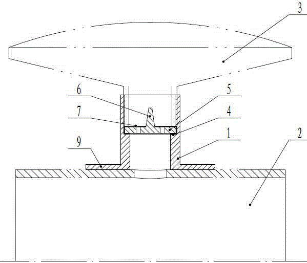
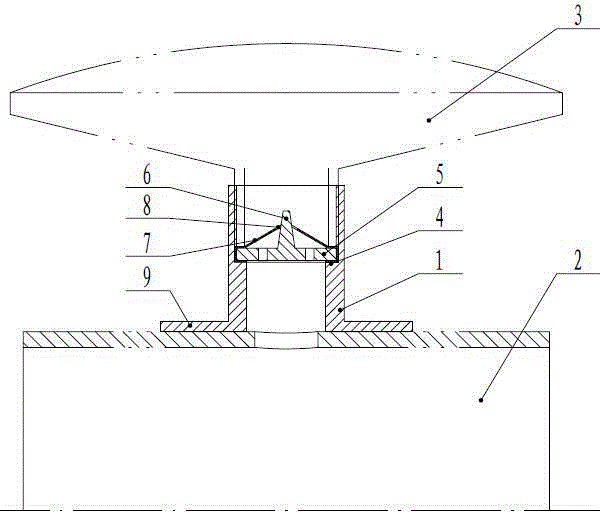
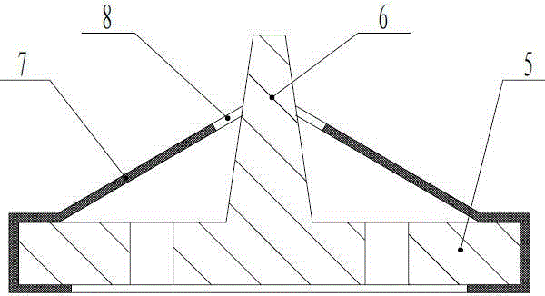
[0025] Such as figure 1 , figure 2 , image 3 As shown, a saddle seat with a backstop device includes a pipe body 1, and the lower end of the pipe body 1 can be fixedly installed on the air delivery pipe 2. In this embodiment, the saddle-shaped seat plate 9 is tightly bonded On the surface of the air delivery pipe 2, the upper end of the pipe body 1 can be fixedly installed with the aeration pan 3, when it is fixedly installed on the air delivery pipe 2, a through hole for ventilation to the pipe body 1 is provided on the air delivery pipe 2 , a backstop device can be fixedly installed in the pipe body 1; the backstop device includes a plate body 5, and a through hole for ventilating the aeration disc 3 and an upwardly protruding cone column 6 are arranged on the plate body 5. The body 5 is covered with an elastic film 7, and the elastic film 7 is provided with a through hole 8 corresponding to the position and shape of the cone column 6, and the periphery of the elastic fi...

Embodiment 2

[0029] Such as Figure 4 As shown, the difference between the second embodiment and the first embodiment is that the compression structure is a short pipe 11, and the aeration pan 3 is also provided with corresponding external threads, and can be installed on the top of the short pipe 11.

Embodiment 3

[0031] Such as Figure 5 As shown, the difference between Embodiment 3 and Embodiment 1 is that the compression structure is a long pipe 12, the upper end of the long pipe 12 is flush with the upper end of the pipe body 1, and the inner hole of the long pipe 12 is also provided with an internal thread. The air disc 3 can be connected with the saddle by the external thread corresponding to the internal thread of the long pipe 12 .

[0032] check valve,

[0033] Such as Figure 6 As shown, a check valve includes a valve body that can be connected to pipelines on both sides, and a check device is fixed in the valve body 10; the check device includes a plate body 5, and a through hole is provided on the plate body 5 And the cone column 6 protruding to one side, the side with the cone column 6 on the plate body 5 is covered with an elastic film 7, and the elastic film 7 is provided with a transparent hole corresponding to the position and shape of the cone column 6. Hole 8, the ...


PUM


Abstract

The invention discloses a saddle with a non-return device. The saddle comprises a pipe body. The non-return device can be fixedly arranged inside the pipe body. The non-return device comprises a plate body. A vent hole for conducting ventilation towards an aeration disc and an upward-protruding conical column are arranged on the plate body. The plate body is coated with an elastic film. A through hole corresponding to the conical column in position and shape is formed in the elastic film. The periphery of the elastic film is fixedly connected with the plate body. When a wind conveying pipe conducts ventilation towards the pipe body, the elastic film bulges upwards and can conduct ventilation towards the aeration disc through the through hole in the elastic film; when the wind conveying pipe stops ventilation towards the pipe body, the elastic film retracts downwards and can close a gap between the through hole in the elastic film and the conical column. According to the saddle, the function of conducting ventilation towards the aeration disc of the saddle is achieved, the aeration disc and the wind conveying pipe are separated when ventilation towards the aeration disc is stopped, and sewage is prevented from entering the wind conveying pipe through the saddle.

Description

technical field [0001] The invention relates to a sewage treatment device, in particular to a saddle for connecting an air pipe and an aeration pan. The invention also relates to a pipeline valve, especially a check valve. Background technique [0002] In the aeration pan aeration system of sewage treatment, the aeration pan is connected with the air pipe through the saddle. The saddle includes a pipe body, the lower end of the pipe body is fixedly installed on the air pipe, and the upper end of the pipe body is fixedly installed with an aeration disc; the air pipe is provided with a through hole for ventilation to the pipe body; the air pipe passes through the saddle To ventilate the aeration pan, the aeration pan aerates the sewage through the micropores arranged on its surface film layer. The existing saddle is not equipped with a backstop device, and when the aeration pan installed on the saddle falls off or breaks, sewage will be poured into the air delivery pipe, aff...

Claims


Application Information

Patent Timeline
Patent Type & Authority Applications(China)
IPC IPC(8): C02F7/00F16K15/14
CPCY02W10/10
Inventor 胡海平
Owner 胡海平
Learn More