Lifting and compressing structure of underfloor furnace door

A compact structure, bottom-mounted technology, applied in furnaces, heat treatment furnaces, furnace components, etc.

Active Publication Date: 2015-12-16
SUZHOU LONGRAY THERMAL TECH
View PDF4 Cites 0 Cited by
  • Summary
  • Abstract
  • Description
  • Claims
  • Application Information

AI Technical Summary

Problems solved by technology

[0003] The purpose of the present invention is to provide a bottom-mounted furnace door lifting and compacting structure to solve the problem of simple and effective lifting and compacting of the bottom-mounted furnace body

Method used


Image

  • Lifting and compressing structure of underfloor furnace door
  • Lifting and compressing structure of underfloor furnace door
  • Lifting and compressing structure of underfloor furnace door

Examples


Embodiment Construction

[0023] The specific implementation manners of the present invention will be further described below in conjunction with the accompanying drawings, so as to make the technical solution of the present invention easier to understand and grasp.

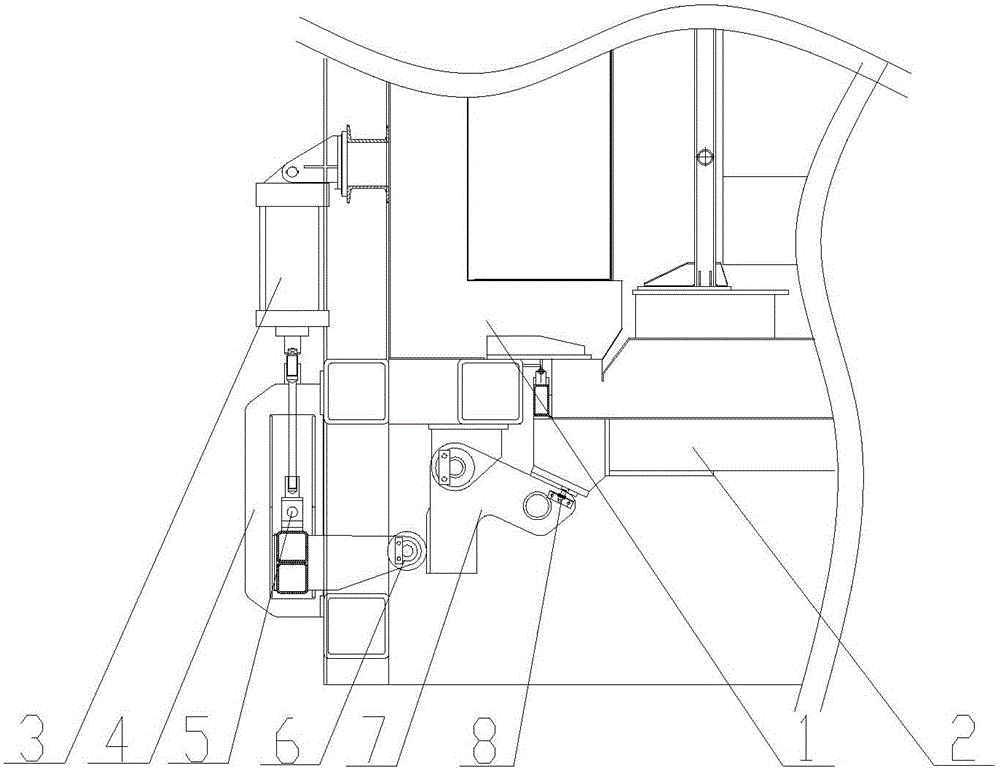
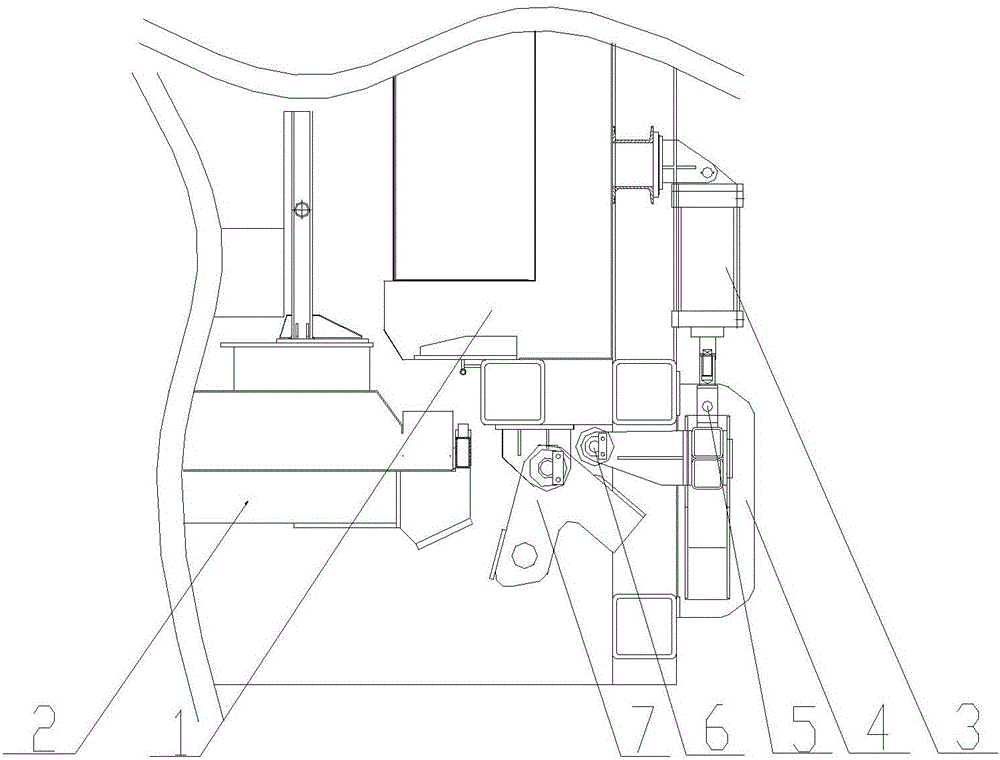
[0024] Such as figure 1 and figure 2 As shown: the lifting and pressing structure of the bottom-mounted furnace door of the present invention includes a cylinder 3, a guide support 4, a slider device 5, a supporting roller 6 and a pressing support frame 7, and the cylinder 3 is installed on the outside of the furnace body 1. The cylinder head is connected with the slider device 5, and the slider device 5 is installed in the guide support 4, and the slider device 5 can slide up and down in the guide support 4. The support roller 6 includes a support base 20 and a roller 17 , one end of the support base 20 is fixedly connected to the slider device 5 , and the other end is fixedly connected to the roller 17 . The compression support frame...


PUM


Abstract

The invention discloses a lifting and compressing structure of an underfloor furnace door. The lifting and compressing structure comprises air cylinders, sliding block devices, support rollers and compressing support frames, wherein each sliding block device is connected with the air cylinder head of the corresponding air cylinder; each support roller is fixedly connected with the corresponding sliding block device; each compressing support frame comprises a compressing seat, a connecting plate, a support framework and a rotating shaft; the compressing seat is mounted near the furnace door; the connecting plate is fixedly connected to the lower part of the compressing seat; the rotating shaft is mounted on the connecting plate; the support framework adopts a V-shaped or right-angle structure; the bending part of the support framework is connected with the rotating shaft; one free end of the support framework is near the furnace door, and the other free end is near the corresponding support roller. The lifting and compressing structure is compact in structure, reliable in motion and flexible in tilting and rotation, and the lifting, compressing and loosening motions for the underfloor furnace door can be well realized; the scheme can be widely applied to single-zone annealing furnaces, the production cost of a single-zone furnace door compressing device is reduced, and greater improvement space in popularization and application of the single-zone furnaces is achieved.

Description

technical field [0001] The invention relates to a locking device for an annealing furnace door, in particular to a lifting and pressing structure for a bottom-mounted furnace door. Background technique [0002] In order to improve the metal properties of the rolled aluminum coil, it is necessary to anneal the rolled aluminum coil. Aluminum coil annealing heat treatment is generally carried out in an annealing furnace. With the vigorous development of the aluminum processing industry, small batch orders are also indispensable for aluminum processing manufacturers. Therefore, single-zone furnaces specially for small batch orders came into being. In order to save the space configuration of the single-zone furnace, the furnace door of the single-zone furnace mostly adopts the bottom-mounted type. However, the simple and effective lifting and pressing problem of the bottom-mounted furnace door has always hindered the promotion of the single-zone furnace. Contents of the invent...

Claims


Application Information

Patent Timeline
IPC IPC(8): C21D9/00F27D1/18
Inventor 张信千陈景阁余广松曹炼朱琴
Owner SUZHOU LONGRAY THERMAL TECH
Why Eureka
Try Eureka