
Composite buffer guardrail

A composite guardrail technology, applied to roads, road safety devices, roads, etc., can solve the problems of metal guardrails such as hardness, loss, and large injuries to vehicles and people, and achieve increased impact resistance, toughness and elasticity, and slowing down The effect of releasing impact energy

Active Publication Date: 2017-04-26
白峻光 +3
View PDF6 Cites 0 Cited by
  • Summary
  • Abstract
  • Description
  • Claims
  • Application Information

AI Technical Summary

Problems solved by technology

[0002] In the past technology, the expressway guardrail is composed of metal fence boards and metal ground piles. In order to make the guardrail reach a certain strength, the ground piles are required to be driven to the hard soil layer, and the interval between the ground piles and the installation position on the fence is fixed. When it reaches the soft soil or stone base, it will cause great difficulties to the installation of the guardrail, which requires rock drilling and earth excavation; when in use, the metal fence can play a role in stopping general collision accidents, but when encountering high-speed When driving a car on the road or a passenger car or truck with a large volume and weight, the protective effect of the guardrail is limited. There are often accidents where a passenger car or truck rushes out of the guardrail and falls into a ditch or river, or even rushes into the opposite lane, causing greater losses or For secondary disasters, the metal guardrail is hard and cannot well relieve the impact energy, causing greater damage to the car and people involved in the accident, and the metal guardrail cannot be used after impact deformation. Play the role of stopping and protecting

Method used


Image

  • Composite buffer guardrail
  • Composite buffer guardrail

Examples


Embodiment Construction

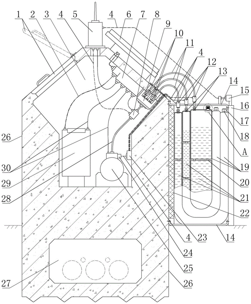
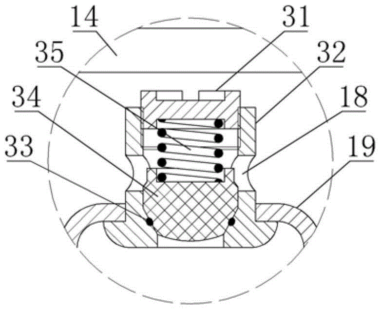
[0018] The composite buffer guardrail has a base body 26, and a buffer device is installed on one side of the base body. The buffer device has a nylon inner plate 22, a nylon outer plate 16 and a water bag 19, and the water bag is provided with a water inlet 13 and a pressure valve 17. The two sides of the water bag are respectively movable and crimped with the nylon inner plate and the nylon outer plate, the other side of the nylon inner plate is fixedly connected with the substrate, and the nylon outer plate is articulated with the substrate through the connecting belt 14 . The base body is a reinforced concrete prefabricated body. The length of the base body in the straight section is more than 5 meters. The base body in the turning section should be prefabricated to increase the overall weight and strength and resist the impact force; the nylon inner plate is fixed with the base body through embedded bolts. , the thickness of the nylon inner plate is 5-20 millimeters; the t...


PUM


Abstract

A combined buffering guardrail is used for buffering impacting force of vehicles and reducing damage of traffic accidents. A buffering device is arranged on one side of a base body of the combined buffering guardrail and provided with a nylon inner plate, a nylon outer plate and a water bag. The water bag is provided with a water adding port and a pressure valve. The two sides of the water bag are movably connected with the nylon inner plate and the nylon outer plate respectively in a pressed manner. The other side of the nylon inner plate is fixedly connected with the base body. The nylon outer plate is connected with the base body in a hanging manner through a connecting band. A threading hole is formed in the lower portion of the base body. The base body is a reinforced concrete base body. An equipment bin is arranged in the base body and internally provided with a gas pump, a storage battery, a distributor and a gas flow dividing valve. The base body is provided with a solar power generating assembly and a wireless signal emitting device. The capacity of water of the water bag is 50-90% of the interior capacity of the water bag. A displacement sensor is arranged on the nylon outer plate. A signal emitting output port of the displacement sensor is connected with a signal input port of the wireless signal emitting device.

Description

technical field [0001] The invention relates to the structure of highway guardrails, and in particular provides a composite buffer guardrail. Background technique [0002] In the past technology, the expressway guardrail is composed of metal fence boards and metal ground piles. In order to make the guardrail reach a certain strength, the ground piles are required to be driven to the hard soil layer, and the interval between the ground piles and the installation position on the fence is fixed. When it reaches the soft soil or stone base, it will cause great difficulties to the installation of the guardrail, which requires rock drilling and earth excavation; when in use, the metal fence can play a role in stopping general collision accidents, but when encountering high-speed When driving a car on the road or a passenger car or truck with a large volume and weight, the protective effect of the guardrail is limited. There are often accidents where a passenger car or truck rushes...

Claims


Application Information

Patent Timeline
Patent Type & Authority Patents(China)
IPC IPC(8): E01F15/02
Inventor 白峻光白岩松白凇会刘艳萍
Owner 白峻光
Learn More