
Aerial photography damping damper

A shock-absorbing damping and damper technology, which is applied in the direction of shock absorbers, springs/shock absorbers, shock absorbers, etc., can solve the problems of potential safety hazards, poor load-bearing capacity and mechanical strength of shock-absorbing balls, and achieve the elimination of safety problems. Hidden danger, good mechanical strength and load-bearing capacity, and the effect of suppressing high-frequency vibration

Inactive Publication Date: 2015-12-16
HARBIN INST OF TECH
View PDF8 Cites 6 Cited by
  • Summary
  • Abstract
  • Description
  • Claims
  • Application Information

AI Technical Summary

Problems solved by technology

[0003] The purpose of the present invention is to solve the problem that the shock-absorbing ball used by the aerial photography shock-absorbing mechanism of the existing aircraft has poor load-bearing capacity and mechanical strength, and has potential safety hazards. The present invention provides an aerial photography shock-absorbing damper

Method used


Image

  • Aerial photography damping damper
  • Aerial photography damping damper
  • Aerial photography damping damper

Examples


specific Embodiment approach 1

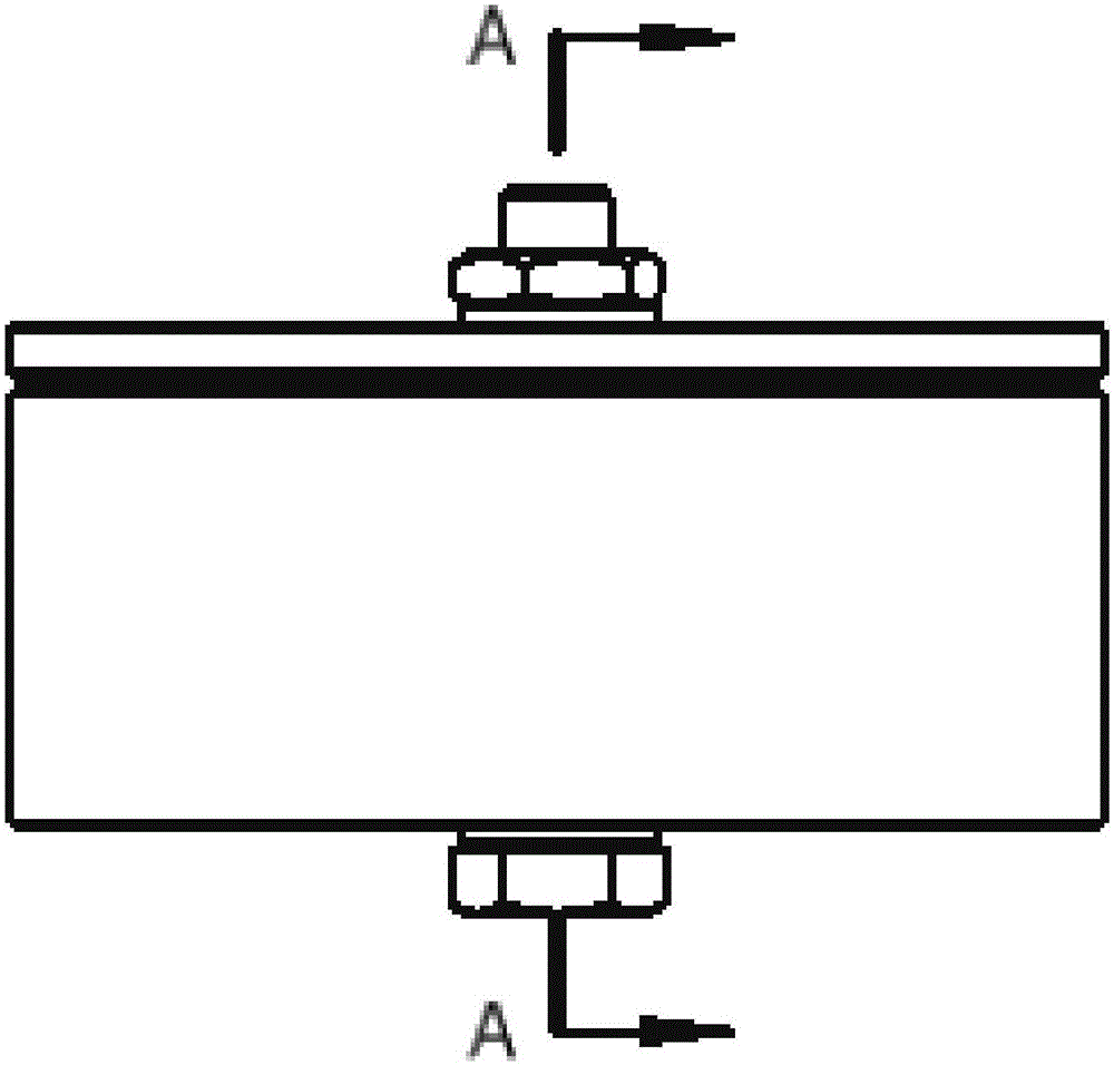
[0023] Specific implementation mode 1: Combination Figure 3 to Figure 6 To illustrate this embodiment, an aerial damping damper described in this embodiment includes a viscoelastic material filling layer 1, an upper damper shell 2, a lower damper shell 3, a fixing member, and a buffer spring 6;

[0024] The upper shell plate 2 of the damper and the lower shell plate 3 of the damper are fixedly connected by a fixing member. A gap is formed between the outer side wall of the upper damper shell plate 2 and the inner side wall of the lower damper shell plate 3, and the gap is filled with viscoelasticity Material filling layer 1;

[0025] The fixing piece passes through the center of the upper damper shell 2 and the lower damper shell 3, the buffer spring 6 is sleeved on the fixing piece, and the two ends of the buffer spring 6 are respectively fixed to the upper damper shell 2 and the lower damper shell In the groove of 3, the free length of the buffer spring 6 is greater than the d...

specific Embodiment approach 2

[0027] Embodiment 2: This embodiment is a further limitation of the aerial damping damper described in Embodiment 1. The outer side wall of the upper damper shell 2 and the inner side wall of the lower damper shell 3 are Slope parallel to each other.

[0028] In this embodiment, the viscoelastic material filling layer 1 is made of viscoelastic material, and the tangential vibration is mainly composed of the viscoelastic material 1 through the shear deformation of the upper shell plate 2 of the damper and the lower shell plate 3 of the damper. The purpose of dissipating vibration energy.

specific Embodiment approach 3

[0029] Specific embodiment three: this embodiment is a further limitation of the aerial damping damper described in specific embodiment two, and the viscoelastic material filling layer 1 reaches the maximum.

[0030] In this embodiment, the larger the volume of the viscoelastic material filling layer 1 is, the more vibration energy is dissipated.


PUM


Abstract

The invention provides an aerial photography damping damper and relates to a damper. The problems that a damping ball utilized for an existing aircraft aerial photography damping mechanism is poor in load bearing capability and mechanical strength and potential safety hazards occur are solved. The damper comprises a viscous-elastic material filling layer, a damper upper shell plate, a damper lower shell plate, a fixed part and a buffer spring. The damper upper shell plate and the damper lower shell plate are fixedly connected through the fixed part, and a gap is formed between the outer side wall of the damper upper shell plate and the inner side wall of the damper lower shell plate. The gap is filled with the viscous-elastic material filling layer, the fixed part penetrates the damper upper shell plate and the center of the damper lower shell plate, the buffer spring sleeves the fixed part, the two ends of the buffer spring are fixed on the damper upper shell plate and the damper lower shell plate respectively, and the free length of the buffer spring is larger than the interval between the damper upper shell plate and the damper lower shell plate. The aerial photography damping damper is used for damping an aerial photography aircraft.

Description

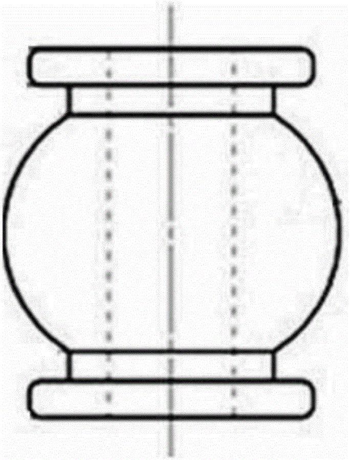
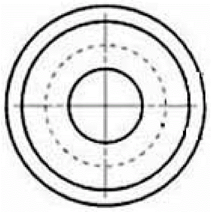
Technical field [0001] The invention relates to a damper, in particular to an aerial photography shock-absorbing damper. Background technique [0002] High-frequency jitter is a huge problem for aerial photography aircraft. Existing aircraft will produce high-frequency vibrations of different frequencies during flight, resulting in serious aerial image distortion. The existing mechanical damping method generally achieves anti-shake by adding damping balls, that is, adding two layers of damping plates between the aircraft and the aerial photography gimbal, connecting with damping balls in the middle, and using the characteristics of damping balls to absorb shock , The shock-absorbing ball structure is such as figure 1 with figure 2 Shown. However, the hardness and load-bearing capacity of the shock-absorbing ball are poor, and it is not suitable when the camera equipment and the gimbal are too heavy. Secondly, the shock-absorbing ball is easy to wear and age, which will bring sa...

Claims


Application Information

Patent Timeline
IPC IPC(8): F16F7/104
Inventor 孙光辉周承邦许林杨刘小磊胡延旭郑辉吴庭丞徐世东
Owner HARBIN INST OF TECH
Learn More