Multi-tube-row integrated header automatic adjusting dispensing condenser

An automatic adjustment and integrated technology, applied in steam/steam condensers, tubular elements, heat exchanger shells, etc., can solve the constraints of the application range of condensers due to liquid separation technology effects, without considering micro-scale diameter heat exchange tubes, Problems such as the inability of the gas-liquid separator to separate liquid reasonably, to avoid fixing and pipe welding, improve the uniformity of working fluid distribution, and improve the flow and heat transfer performance

Active Publication Date: 2015-12-16
广西高而美节能科技有限公司
View PDF5 Cites 14 Cited by
  • Summary
  • Abstract
  • Description
  • Claims
  • Application Information

AI Technical Summary

Problems solved by technology

Existing separatory condensers all adopt a single-tube row structure, and the diameter of the heat exchange tubes is of a conventional scale, and micro-scale heat exchange tubes (micro-channels) are not considered. There are large limitations in heat exchange capacity (single tube row), large amount of liquid working fluid brought out with the gas phase working medium (conventional header and heat exchange tube end structure), and gas-liquid separator cannot reasonably separate liquid according to working conditions (opening holes Cross-section fixed) and other issues, the effect of liquid separation technology and the application range of the condenser are greatly restricted
At present, there is no integrated header structure shared by too many tube rows in the liquid separator condenser (the so-called integrated header structure is a structure in which multiple rows of heat exchange tubes are connected in parallel into the same header to make fluids mix), and the existing header The box (the tube insertion surface is arc-shaped) is not conducive to the processing of multi-column condensers and the effect of preventing liquid from being carried out by gas is poor
In addition, due to the inhomogeneity of the heat transfer between the front and rear tube rows of the multi-column air-cooled microchannel condenser, the flow and heat transfer between the tube rows during the subsequent condensation process will deteriorate.

Method used


Image

  • Multi-tube-row integrated header automatic adjusting dispensing condenser
  • Multi-tube-row integrated header automatic adjusting dispensing condenser
  • Multi-tube-row integrated header automatic adjusting dispensing condenser

Examples


Embodiment Construction

[0027] The present invention will be described in detail below in conjunction with the accompanying drawings and specific embodiments.

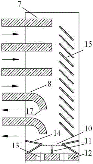
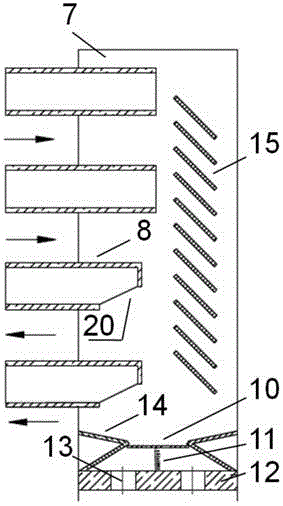
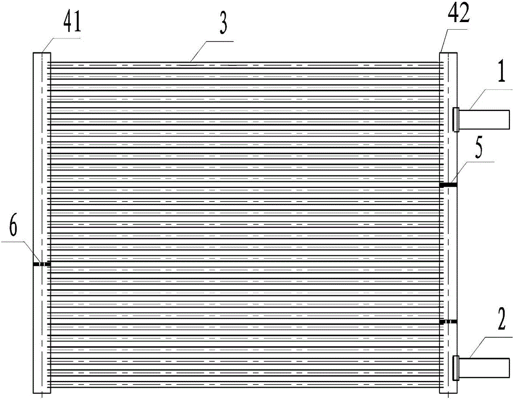
[0028] Multi-pipe row integrated header with automatic adjustment liquid separation condenser, such as Figure 1-5 As shown, it includes a first header 41, a second header 42 and heat exchange tubes 3, and several heat exchange tubes 3 are arranged in parallel between the first header 41 and the second header 42. The inner cavity of the heat exchange tube 3 communicates with the inner cavity of the first header 41 and the second header 42, and the inlet pipe 1 and the outlet pipe 2 are installed on the first header 41 or the second header 42. A partition 5 is arranged in the header (the first header 41 or the second header 42) where the inlet pipe 1 is installed, and a gas-liquid separator 6 is arranged in the first header 41 and the second header 42; The outlet pipe section 8 of the heat exchange tube 3 (at the outlet of the medium) extends...


PUM


Abstract

The invention discloses a multi-tube-row integrated header automatic adjusting dispensing condenser, comprising a first header, a second header, and heat exchange tubes. The header which is provided with an inlet pipe is provided with septums. The first header and the second header are internally provided with gas-liquid separators. The outlet tube segments of the heat exchange tubes extend into the cavity of the header, and the ends of the outlet tube segments bend downward. Or the outlet tube segments of the heat exchange tubes extend into the cavity of the header, and the outlet tube segments of the heat exchange tubes beveling downward from the diameter of the outlet tube segment and form bevel connections. Beneficial technical effects of the condenser are that heat transfer flowing performance of the condenser is improved, uniformity of working medium distribution is effectively improved, flow resistance is greatly reduced and high-efficiency heat exchange is maintained, a condensate liquid is prevented from being brought out of the headers, so as to greatly improve dispending effect of the headers on two ends, high-efficiency heat exchange flow state in tubes can be maintained on the tail of the condenser and under condition of lower area flow, and effect of enhancing heat transfer based on a dispensing condensing principle is improved.

Description

【Technical field】 [0001] The invention relates to the field of condensers, in particular to a multi-pipe-row integrated header box automatic adjustment liquid separation condenser. 【Background technique】 [0002] Existing condensers using liquid separation technology are limited to single-row heat exchange tubes, rather than multi-tube liquid-separation condensers. Existing separatory condensers all adopt a single-tube row structure, and the diameter of the heat exchange tubes is of a conventional scale, and micro-scale heat exchange tubes (micro-channels) are not considered. There are large limitations in heat exchange capacity (single tube row), large amount of liquid working fluid brought out with the gas phase working medium (conventional header and heat exchange tube end structure), and gas-liquid separator cannot reasonably separate liquid according to working conditions (opening holes Section fixed) and other issues, so that the effect of liquid separation technology...

Claims


Application Information

Patent Timeline
Patent Type & Authority Applications(China)
IPC IPC(8): F28B1/00F28F9/04F28F9/00F28F1/12
Inventor 陈颖钟天明杨庆成罗向龙郑文贤莫松平
Owner 广西高而美节能科技有限公司
Why Eureka
Try Eureka