Encoder

An encoder and collector technology, applied in the field of encoders, can solve the problems of increasing the outer diameter of the encoder, the large outer diameter, and the inability to meet application requirements, etc.

Inactive Publication Date: 2015-12-16
CHANGCHUN SANFENG PHOTOELECTRONICS INSTR MFG
View PDF5 Cites 7 Cited by
  • Summary
  • Abstract
  • Description
  • Claims
  • Application Information

AI Technical Summary

Problems solved by technology

[0003] In the prior art, if you want to increase the number of coding bits and coding accuracy of the encoder, you need to increase the number of code tracks in the grating disc, which will obviously lead to an increase in the outer diameter of the encoder
Therefore, the outer diameter of high-digit encoders in the prior art is relatively large, which cannot meet the application requirements in some equipment

Method used


Image

  • Encoder

Examples


Embodiment Construction

[0021] In order to enable those skilled in the art to better understand the technical solutions in the present invention, the technical solutions in the embodiments of the present invention will be clearly and completely described below in conjunction with the drawings in the embodiments of the present invention. Obviously, the described The embodiments are only some of the embodiments of the present invention, not all of them. Based on the embodiments of the present invention, all other embodiments obtained by persons of ordinary skill in the art without making creative efforts shall fall within the protection scope of the present invention.

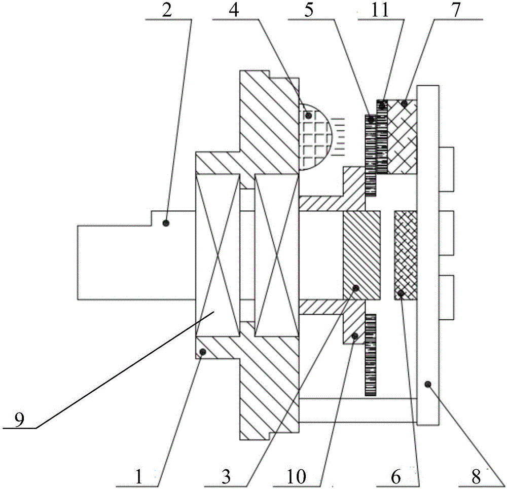
[0022] Please refer to figure 1 , figure 1 Shown is a schematic diagram of an axial section of an encoder provided by an embodiment of the present invention. The encoder provided in this embodiment includes a base 1, a spindle 2, a magnetic source body 3, a light emitting element 4, a grating disk 5, a magnetic collector 6, an optical...


PUM


Abstract

The invention discloses an encoder comprising a pedestal, a main shaft, a magnetic source body, a light-emitting element, a grating disc, a magnetic acquisition device, an optical acquisition device and a circuit board. The main shaft penetrates through the pedestal in an axial direction, and the main shaft and the pedestal can relatively rotate. The magnetic source body and the grating disc are arranged at the internal end part of the main shaft. The magnetic source body is arranged at the axis of the main shaft. The grating disc and the main shaft are coaxially connected. The light-emitting element is arranged on the pedestal. The optical acquisition device and the light-emitting element are oppositely arranged. The optical signals emitted by the light-emitting element are received by the optical acquisition device through the grating disc. The magnetic acquisition device and the magnetic source body are oppositely arranged, and the magnetic acquisition device is used for receiving magnetic signals emitted by the magnetic source body. The optical acquisition device and the magnetic acquisition device are connected with the circuit board. According to the encoder, photoelectric encoding and magnetoelectric encoding are combined so that high-digit encoding can be realized and the application requirement of small external diameter can be met.

Description

technical field [0001] The invention relates to the technical field of photoelectric devices, in particular to an encoder. Background technique [0002] An encoder is a rotary sensor that converts angular displacement into a series of digital pulses. The basic structure of an encoder includes a spindle, a light-emitting element, a grating disc, and a receiving element. When the encoder spindle drives the grating disk to rotate, the light emitted by the light-emitting element is cut into intermittent light by the grating disk, and is received by the receiving element to generate an initial signal, which is processed by a subsequent circuit and outputs a pulse signal for further signal transmission. [0003] In the prior art, if it is desired to increase the number of coding bits and the coding accuracy of the encoder, it is necessary to increase the number of code tracks in the grating disc, which obviously leads to an increase in the outer diameter of the encoder. Therefor...

Claims


Application Information

Patent Timeline
Patent Type & Authority Applications(China)
IPC IPC(8): G01D5/32G01D5/12
Inventor 崔峰铭孟昭辉李延星
Owner CHANGCHUN SANFENG PHOTOELECTRONICS INSTR MFG
Why Eureka
Try Eureka