High-voltage switch cabinet capable of being automatically cooled and cleaned

A high-voltage switchgear, automatic cooling technology, applied in substation/switch layout details, substation/switchgear cooling/ventilation, electrical components, etc., can solve the problems of reducing the service life of electrical components, dusty, poor heat dissipation, etc.

Inactive Publication Date: 2015-12-16
STATE GRID CORP OF CHINA +2
View PDF10 Cites 17 Cited by
  • Summary
  • Abstract
  • Description
  • Claims
  • Application Information

AI Technical Summary

Problems solved by technology

At present, the method and structure adopted for heat dissipation of electrical components in the switchgear have the following defects: 1. Since the switchgear is generally high in height, vertical ventilation is adopted, the air path is long, and the cold air at the end of the air path has been heated. Therefore, the temperature in the switch cabinet is still high, and the heat dissipation effect is poor, which leads to shortened service life of electrical components; 2. There is more dust at the air inlet of the air duct, so that the wind entering the switch cabinet carries more dust; 3. The electrical components are long-term After use, dust is easy to accumulate in the depressions and irregular protrusions of electrical components, which reduces the service life of electrical components and creates potential safety hazards (possibly causing short circuits); Larger, low cooling efficiency

Method used


Image

  • High-voltage switch cabinet capable of being automatically cooled and cleaned
  • High-voltage switch cabinet capable of being automatically cooled and cleaned
  • High-voltage switch cabinet capable of being automatically cooled and cleaned

Examples


Embodiment Construction

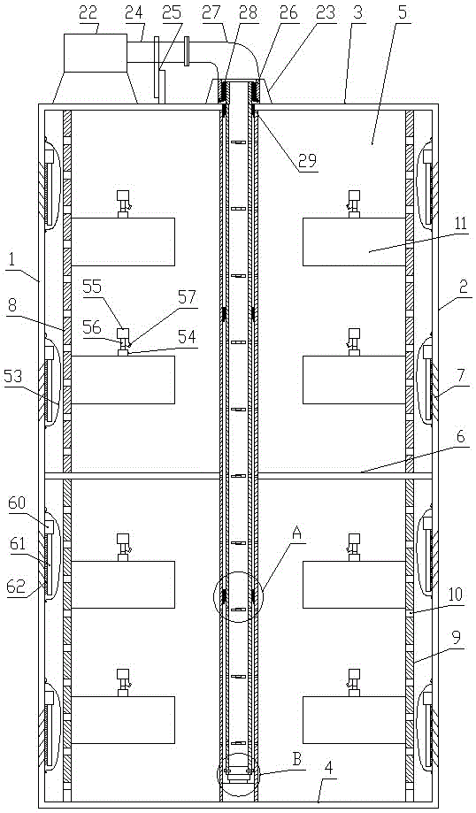
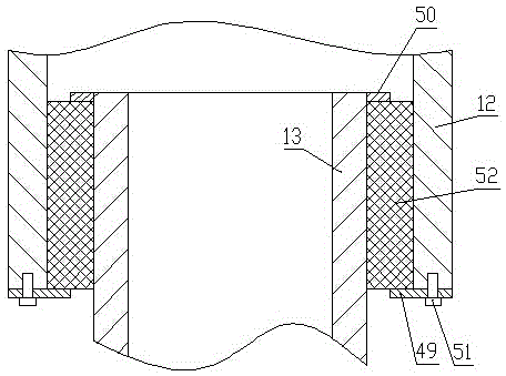
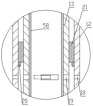
[0028] Such as Figure 1-Figure 7 As shown, the automatic cooling and cleaning high-voltage switchgear of the present invention includes a cabinet in the shape of a cuboid, and the cabinet consists of a left side panel 1, a right side panel 2, a top panel 3, a bottom panel 4, a rear side panel 5 and a cabinet door (Fig. not shown in ), a partition 6 is arranged horizontally between the left side panel 1 and the right side panel 2, shutters 7 are respectively arranged on the left side panel 1 and the right side panel 2, and the inner wall of the left side panel 1 and the right side panel 2 The inner wall is provided with a cleaning mechanism at the shutter 7, and a left vertical board 8 and a right vertical board 9 are arranged between the top board 3 and the bottom board 4, the left vertical board 8 is parallel to and adjacent to the left side board 1, and the right vertical board 9 is connected to the The right side plate 2 is parallel and adjacent, and the left vertical plat...


PUM


Abstract

The invention provides a high-voltage switch cabinet capable of being automatically cooled and cleaned. The high-voltage switch cabinet comprises a cuboidal cabinet body which is composed of a left side plate, a right side plate, a top plate, a bottom plate, a back side plate and cabinet doors; the left side plate and the right side plate are each provided with a blind window, and the inner wall of the left side plate and the inner wall of the right side plate are provided with dust removing mechanisms at the blind windows; a left vertical plate and a right vertical plate are arranged between the top plate and the bottom plate, the left vertical plate is parallel to and adjacent to the left side plate, the right vertical plate is parallel to and adjacent to the right side plate, air suction holes are evenly formed in the left vertical plate and the right vertical plate, and the right side of the left vertical plate and the left side of the right vertical plate are provided with electric elements; an air volume rotating regulating mechanism is arranged between the center of the top plate and the center of the bottom plate. The high-voltage switch cabinet has the advantages of being simple in structure, easy to operate, good in heat dissipation effect, little in energy consumption, high in reliability and good in dust-proof effect, the electric elements in the cabinet body can keep the good working state temperature by regulating the air sucking volume, and therefore the service life of the electric elements is prolonged.

Description

technical field [0001] The invention relates to electrical equipment, in particular to an automatic cooling and cleaning high-voltage switchgear. Background technique [0002] Switchgear is commonly used electrical equipment in the power industry. The heat generated by the electrical components installed in the switchgear needs to be discharged continuously to ensure the normal operation of the electrical components. At present, the method and structure adopted for heat dissipation of electrical components in the switchgear have the following defects: 1. Since the switchgear is generally high in height, vertical ventilation is adopted, the air path is long, and the cold air at the end of the air path has been heated. Therefore, the temperature in the switch cabinet is still high, and the heat dissipation effect is poor, which leads to shortened service life of electrical components; 2. There is more dust at the air inlet of the air duct, so that the wind entering the switch ...

Claims


Application Information

Patent Timeline
Patent Type & Authority Applications(China)
IPC IPC(8): H02B1/56H02B1/28
CPCH02B1/565H02B1/28
Inventor 杨晓舟孙朝伟张丽卢磊刘亚辉张挺周方王肖萌
Owner STATE GRID CORP OF CHINA
Why Eureka
Try Eureka