Micro power generation method and micro power generation device
A power generation device and micro technology, which can be applied to electromechanical devices, electrical components, etc., can solve the problems of battery environment, increase in use cost, restrictions, etc., and achieve the effects of low cost, simple structure and high efficiency
- Summary
- Abstract
- Description
- Claims
- Application Information
AI Technical Summary
Problems solved by technology
Method used
Image

Examples
Embodiment 1
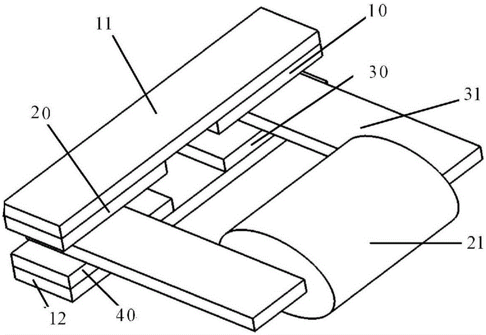
[0026] Embodiment 1: as figure 2 Shown, a kind of miniature generating device, the first permanent magnet 10 and the second permanent magnet 20 are fixed on the lower surface of the first back iron 11, the third permanent magnet 30 and the fourth permanent magnet are fixed on the upper surface of the second back iron 12 40, the conductive coil 21 is wound in the middle of the U-shaped magnetic permeable frame 31, and one side plate of the U-shaped magnetic permeable frame 31 is located in the space between the second permanent magnet 20 and the fourth permanent magnet 40, and the U-shaped magnetic permeable frame 31 The other side plate is located in the space between the first permanent magnet 10 and the third permanent magnet 30,
[0027] The S pole of the first permanent magnet 10 and the N pole of the second permanent magnet 20 face the upper surface of the U-shaped magnetically permeable skeleton 31, and the N pole of the third permanent magnet 30 and the S pole of the f...
Embodiment 2
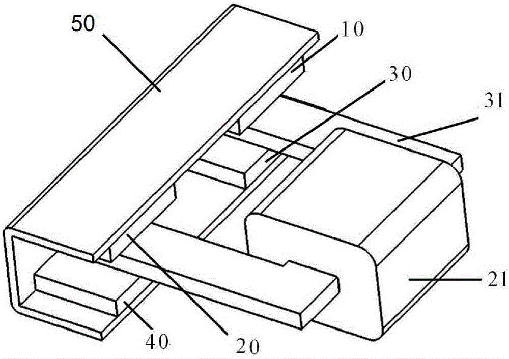
[0031] Such as figure 1 As shown, a kind of miniature power generation device, the back of the first back iron 11 of embodiment 1 and the second back iron 12 are connected into one body through the vertical plate to become the third back iron 50,
[0032] The first permanent magnet 10 and the second permanent magnet 20 are fixed on the lower surface of the inner side of the third back iron 50, and the third permanent magnet 30 and the fourth permanent magnet 40 are fixed on the lower surface of the inner side of the third back iron 50.
[0033] Conductive coil 21 is wound on the middle part of U-shaped magnetic permeable frame 31, one side plate of U-shaped magnetic permeable frame 31 is located in the space between second permanent magnet 20 and fourth permanent magnet 40, and the other side of U-shaped magnetic permeable frame 31 One side plate is located in the space between the first permanent magnet 10 and the third permanent magnet 30,
[0034] The S pole of the first p...
Embodiment 3
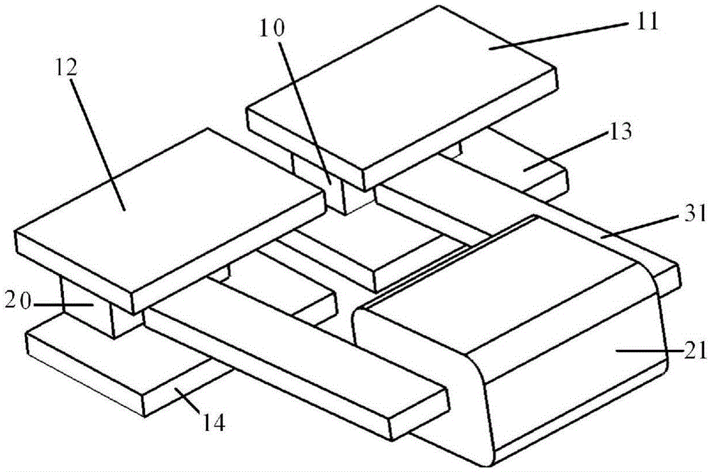
[0037] Embodiment 3: as image 3 as shown,
[0038] A micro power generation device, its structure includes: a first permanent magnet 10, a second permanent magnet 20, a first magnetically conductive sheet 11, a second magnetically conductive sheet 12, a third magnetically conductive sheet 13, a fourth magnetically conductive sheet 14, Conductive coil 21, magnetic permeable skeleton 31.
[0039] The first permanent magnet 10 and the second permanent magnet 20 are placed in parallel and separately;
[0040] The N pole of the first permanent magnet 10 faces upward, the N pole of the first permanent magnet 10 is fixed with a first magnetically conductive sheet 11, and the S pole of the first permanent magnet 10 is fixed with a third magnetically conductive sheet 13;
[0041] The S pole of the second permanent magnet 20 is upward, the S pole of the second permanent magnet 20 is fixed with the second magnetically conductive sheet 12, and the N pole of the second permanent magnet ...
PUM
 Abstract
Description
Claims
Application Information
 - R&D Engineer
- R&D Manager
- IP Professional
- Industry Leading Data Capabilities
- Powerful AI technology
- Patent DNA Extraction
Browse by: Latest US Patents, China's latest patents, Technical Efficacy Thesaurus, Application Domain, Technology Topic.
© 2024 PatSnap. All rights reserved.Legal|Privacy policy|Modern Slavery Act Transparency Statement|Sitemap