Control method and control device
A control method and exposure control technology, applied in the field of image processing, can solve the problems of unfavorable shooting of moving objects, redundant information, and more noise, and achieve the effects of reducing source generation, reducing shooting time, and improving use efficiency
- Summary
- Abstract
- Description
- Claims
- Application Information
AI Technical Summary
Problems solved by technology
Method used
Image

Examples
Embodiment 1
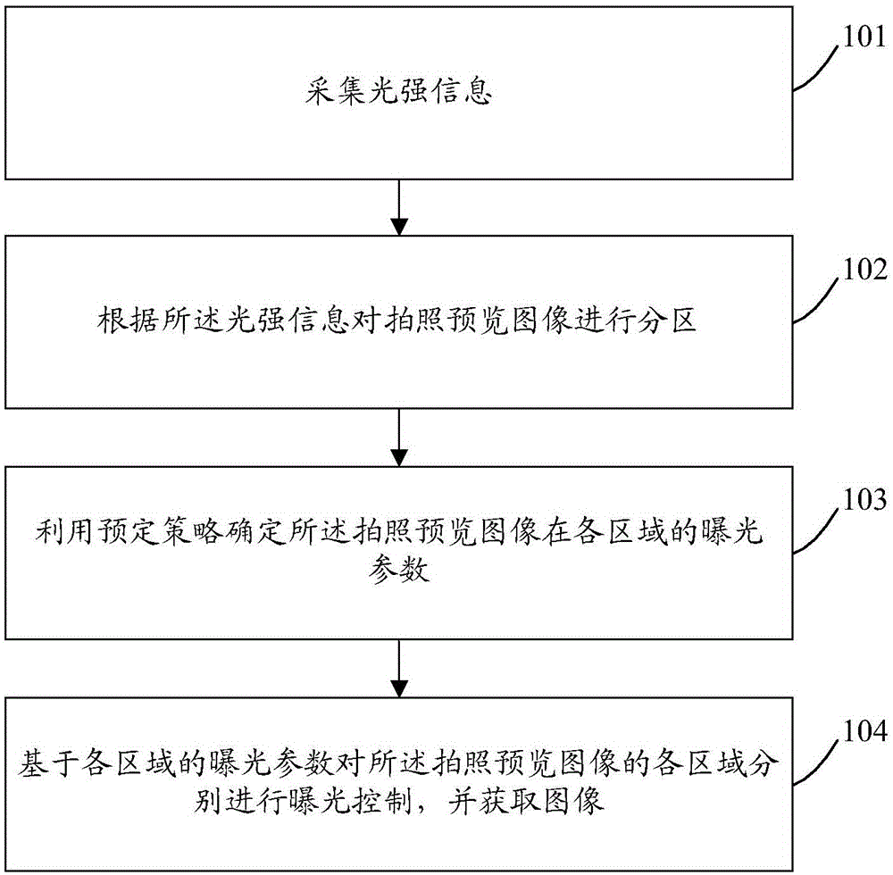
[0066] figure 1It is a schematic diagram of the implementation flow of a control method provided by an embodiment of the present invention. The control method in this embodiment is applied to an electronic device, and the electronic device supports the camera function. In a preferred embodiment of the present invention, the control method It mainly includes the following steps:
[0067] Step 101: Collect light intensity information.
[0068] In this embodiment, the light intensity information may be collected by a sensor.
[0069] Step 102: Partition the photo preview image according to the light intensity information.
[0070] Preferably, said partitioning the photo preview image according to the light intensity information may include:
[0071] Divide light intensity information satisfying the same preset range into a type of light intensity area;
[0072] The photo preview image is divided into N regions corresponding to the light intensity regions; wherein, N is a posi...
Embodiment 2
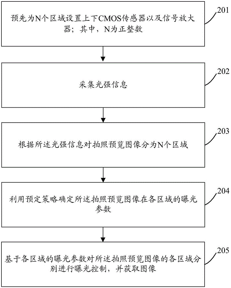
[0106] figure 2 It is a schematic diagram of the implementation flow of another control method provided by the embodiment of the present invention. The control method in this embodiment is applied to an electronic device, and the electronic device supports the camera function. In a preferred embodiment of the present invention, the control The method mainly includes the following steps:
[0107] Step 201: Pre-setting upper and lower CMOS sensors and signal amplifiers for N regions; wherein, N is a positive integer.
[0108] Preferably, N=3.
[0109] That is to say, in order to save cost, block exposure control can be realized; specifically, the CMOS tubes used to control the shutter switching time of each area, and the CMOS tubes used to control each Area ISO signal amplifier.
[0110] Step 202: Collect light intensity information.
[0111] In this embodiment, the light intensity information may be collected by a sensor.
[0112] Step 203: Divide the photo preview image ...
Embodiment 3
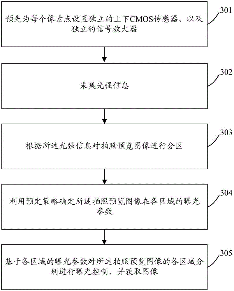
[0142] image 3 It is a schematic diagram of the implementation flow of another control method provided by the embodiment of the present invention. The control method in this embodiment is applied to an electronic device, and the electronic device supports the camera function. In a preferred embodiment of the present invention, the control The method mainly includes the following steps:
[0143] Step 301: Pre-setting independent upper and lower CMOS sensors and independent signal amplifiers for each pixel.
[0144] That is to say, when the chip size and economic conditions permit, each pixel can be assigned a CMOS transistor for controlling the shutter switching time and a signal amplifier for controlling the ISO.
[0145] Step 302: Collect light intensity information.
[0146] In this embodiment, the light intensity information may be collected by a sensor.
[0147] Step 303: Partition the photo preview image according to the light intensity information.
[0148] Preferab...
PUM
 Abstract
Description
Claims
Application Information
 - R&D
- Intellectual Property
- Life Sciences
- Materials
- Tech Scout
- Unparalleled Data Quality
- Higher Quality Content
- 60% Fewer Hallucinations
Browse by: Latest US Patents, China's latest patents, Technical Efficacy Thesaurus, Application Domain, Technology Topic, Popular Technical Reports.
© 2025 PatSnap. All rights reserved.Legal|Privacy policy|Modern Slavery Act Transparency Statement|Sitemap|About US| Contact US: help@patsnap.com