Water outlet device with self-power generating function

A water outlet device and self-generating technology, which is applied in spraying devices, spraying devices with movable outlets, hydroelectric power generation, etc. It can solve the problems that hydroelectric power generation devices cannot generate electricity normally, the charging power of rechargeable batteries is high, and the electromagnetic valve cannot provide electric power. , to achieve the effect of mass production, convenient mass production and compact structure

Active Publication Date: 2015-12-23
FUJIAN XIHE SANITARY WARE TECH
View PDF10 Cites 2 Cited by
  • Summary
  • Abstract
  • Description
  • Claims
  • Application Information

AI Technical Summary

Problems solved by technology

[0004] The method of directly supplying electric energy to the solenoid valve while the hydroelectric generating device generates electric energy is not feasible in the actual application process. This is because the operating power required by the solenoid valve is quite different from the actual output electric power of the hydroelectric generating device, and the two do not match. ; When the initial state of each solenoid valve is closed, the hydroelectric power generation device cannot generate electricity normally, so it cannot provide electric energy to the solenoid valve, so that the solenoid valve cannot be opened
[0005] The use of battery power supply is not conducive to energy saving and environmental protection, and there are potential safety hazards when impacted by external forces or overcharged; rechargeable batteries have high requirements for charging power, and low voltage and low current are difficult to charge.

Method used


Image

  • Water outlet device with self-power generating function
  • Water outlet device with self-power generating function
  • Water outlet device with self-power generating function

Examples


Embodiment 1

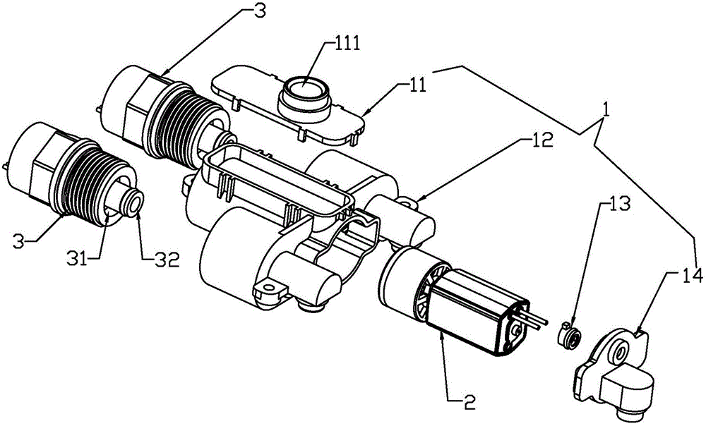
[0054] See Figure 1-Figure 7 Shown, a kind of self-generating water outlet device of the present invention, it comprises:

[0055] The fixed unit 1 is provided with a water inlet 1-a and two first water outlets 1-b (the number of the first water outlets 1-b is not limited to two) and a second water outlet 1-c (the first water outlet 1-c) The number of two water outlets 1-c is not limited to one); each first water outlet 1-b is connected to the water inlet 1-a through an electric control valve respectively, and the second water outlet 1-c is a normally open waterway (ie keep in the water outlet state), and communicate with the water inlet 1-a; the electric control valve is a valve component that uses electricity to control the opening or closing of its internal passage. In this embodiment, the electric control valve is preferably a solenoid valve 3;

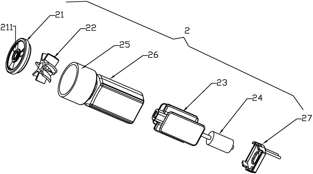
[0056] A power generating mechanism 2, which is installed in the fixed unit 1 and is impacted by the water flowing through the...

Embodiment 2

[0072] See Figure 12 , Figure 13 Shown, a kind of self-generating water outlet device of the present invention, it comprises:

[0073] The fixed unit 1 is provided with a water inlet and two water outlets 1-b (the number of water outlets is not limited to two), and each water outlet 1-b is connected to the water inlet through an electric control valve; and the embodiment In the same way, the electrically controlled valve is preferably realized by a solenoid valve 3;

[0074] A power generating mechanism 2, which is installed on the fixed unit 1 and is impacted by the water flowing through the water inlet to generate electric energy;

[0075] A fast energy storage element for storing the electrical energy generated by the power generating mechanism;

[0076] A control unit, which includes a control circuit and a control module for driving the control circuit to act;

[0077] The control circuit, fast energy storage element, solenoid valve 3, and power generation mechanism...

Embodiment 3

[0085] A self-generating water outlet device of the present invention differs from Embodiment 2 in that one of the solenoid valves is a normally open solenoid valve (a solenoid valve that is in an open state when no power is applied), and the rest of the solenoid valves are normally closed. The electromagnetic valve. The control circuit obtains electric energy through the fast energy storage element and controls each solenoid valve to open or close.

[0086] When water enters the water inlet of the fixed unit, the water enters through the inclined water hole of the power generation mechanism, drives the impeller to rotate, and finally flows out through the normally open solenoid valve and its corresponding outlet. The rotor of the generator moves along with the rotation of the impeller to cut the magnetic field lines, thereby generating an induced potential. The induced potential is drawn out through the terminal and stored in the super capacitor after rectification. The charg...


PUM


Abstract

The invention discloses a water outlet device with a self-power generating function. The water outlet device comprises a fixing unit, a power generating mechanism, a rapid energy storage element and a control unit. The fixing unit is provided with a water inlet way, at least one first water outlet way and at least one second water outlet way, wherein the first water outlet ways are connected with the water inlet way through electronic control valves, and the second water outlet ways are communicated with the water inlet way. The power generating mechanism is mounted on the fixing unit. The control unit comprises a control circuit and a control module. The control circuit, the rapid energy storage element, the electronic control valves and the power generating mechanism are electrically connected, electric energy generated by the power generating mechanism is rectified and then stored in the rapid energy storage element, and the control circuit obtains the electric energy through the rapid energy storage element and controls opening or closing of the electronic control valves. The electric energy generated by the power generating mechanism is stored in the rapid energy storage element first and then output, the enough electric quantity for the control circuit to control opening and closing of the electronic control valves can be provided, energy is saved, and the environment is protected; circulating charging and discharging can be achieved, the service life is long, and potential safety hazards are avoided.

Description

technical field [0001] The invention relates to a bathroom product, in particular to a self-generating water outlet device. Background technique [0002] At present, the showers in the prior art generally have at least two water outlet functions, and can emit at least two kinds of sprays, such as massage water, shower water, and the like. For this type of shower, most of them use mechanical switching methods to switch their water outlet functions, such as rotation switching, swing switching, etc. However, the mechanical switching method is inconvenient to operate, labor-saving, lacks a sense of technology, and cannot keep up with society. development trend. [0003] The utility model patent with the Chinese patent number 200520121206.6 discloses an electromagnetic button shower head, which uses a solenoid valve to cooperate with the button to control the water outlet mode of the shower head, and uses a hydroelectric power generation device to generate electric energy under ...

Claims


Application Information

Patent Timeline
Patent Type & Authority Applications(China)
IPC IPC(8): B05B1/32B05B1/18
CPCB05B1/18B05B1/32Y02B10/50F05B2220/602B05B1/16B05B3/04F03B11/02F03B13/00F05B2240/60Y02E10/20F03B11/004
Inventor 林孝发林孝山刘启乔邓小清顾才波
Owner FUJIAN XIHE SANITARY WARE TECH
Why Eureka
Try Eureka