Supercharge Your Innovation With Domain-Expert AI Agents!

Planing machine

A technology of gantry planer and bed, which is applied in the direction of planer/slotting machine, planer, metal processing equipment, etc., and can solve the problem of high energy consumption

Inactive Publication Date: 2015-12-23
崔天荣
View PDF9 Cites 0 Cited by
  • Summary
  • Abstract
  • Description
  • Claims
  • Application Information

AI Technical Summary

Problems solved by technology

[0003] In order to overcome the problem of high energy consumption of the traditional gantry planer, the invention provides a gantry planer

Method used


Image

  • Planing machine
  • Planing machine
  • Planing machine

Examples


Embodiment Construction

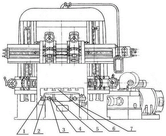
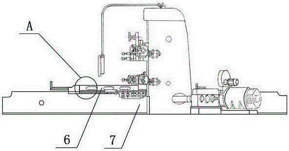
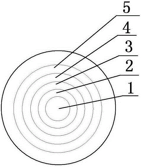
[0009] Such as figure 1 , 2 As shown in and 3, the gantry planer of the present invention includes a worktable 6, a bed 7, a motor, a tool holder, and a column. The lower part of the workbench 6 is provided with two rails and placed in the V groove of the bed 7, such as image 3 The rail shown includes a retaining ring 2, a bearing 3, a wheel 4, and a cap 5 with a retaining ring 2, a bearing 3, a wheel 4, and a cap 5 in sequence with the shaft 1 as the center. figure 2 Inside part A.

[0010] The gantry planer of the present invention can save energy of more than 30% without affecting the accuracy and efficiency, meets the requirements of energy saving and consumption reduction proposed by the state, and is suitable for various types of gantry planers.


PUM


Abstract

The invention discloses a planing machine. The planing machine comprises a working table (6), a machine body (7), a motor, a tool post and a stand column, wherein two rails are arranged at the lower part of the working table (6), and are placed in a V-shaped groove of the machine body (7); and each rail comprises a shaft (1) coated with a retainer ring (2), a bearing (3), a wheel (4) and a cap, the shaft being the center. The planing machine has the following beneficial effects: more than 30% of energy can be saved under the conditions of not influencing the precision and the efficiency, so that the requirements of energy conservation and consumption reduction proposed by the country are met. The invention is applicable to planning machines of different specifications.

Description

Technical field [0001] The invention relates to the field of mechanical processing equipment, in particular to a planer. Background technique [0002] Longben planer is one of the important equipment in mechanical processing. At present, the planer is a single track, which generally has the problem of high energy consumption. Summary of the invention [0003] In order to overcome the problem of high energy consumption of the traditional planer, the present invention provides a planer. [0004] The technical solution adopted by the present invention to achieve the above purpose is: including a worktable 6, a bed 7, a motor, a tool rest, and a column. The lower part of the workbench 6 is provided with two rails and placed in the V groove of the bed 7 , The rail includes a retaining ring 2, a bearing 3, a wheel 4, and a cap 5 with the shaft 1 as the center. [0005] The gantry planer of the present invention can save energy of more than 30% without affecting the accuracy and efficiency...

Claims


Application Information

Patent Timeline
Patent Type & Authority Applications(China)
IPC IPC(8): B23D7/00
Inventor 崔天荣
Owner 崔天荣
Features
  • R&D
  • Intellectual Property
  • Life Sciences
  • Materials
  • Tech Scout
  • Unparalleled Data Quality
  • Higher Quality Content
  • 60% Fewer Hallucinations
Learn More