A dual-focus laser micromachining device and its processing method

A micro-machining and double-focus technology, applied in laser welding equipment, metal processing equipment, manufacturing tools, etc., can solve the problems of poor processing effect and low processing efficiency, increase processing efficiency, improve efficiency and effect, and have a wide range of applications Effect

Active Publication Date: 2018-06-01
深圳市大族微加工软件技术有限公司
View PDF7 Cites 0 Cited by
  • Summary
  • Abstract
  • Description
  • Claims
  • Application Information

AI Technical Summary

Problems solved by technology

The problems of this single-focus laser micromachining device are: low processing efficiency and poor processing effect

Method used


Image

  • A dual-focus laser micromachining device and its processing method
  • A dual-focus laser micromachining device and its processing method
  • A dual-focus laser micromachining device and its processing method

Examples


Embodiment 1

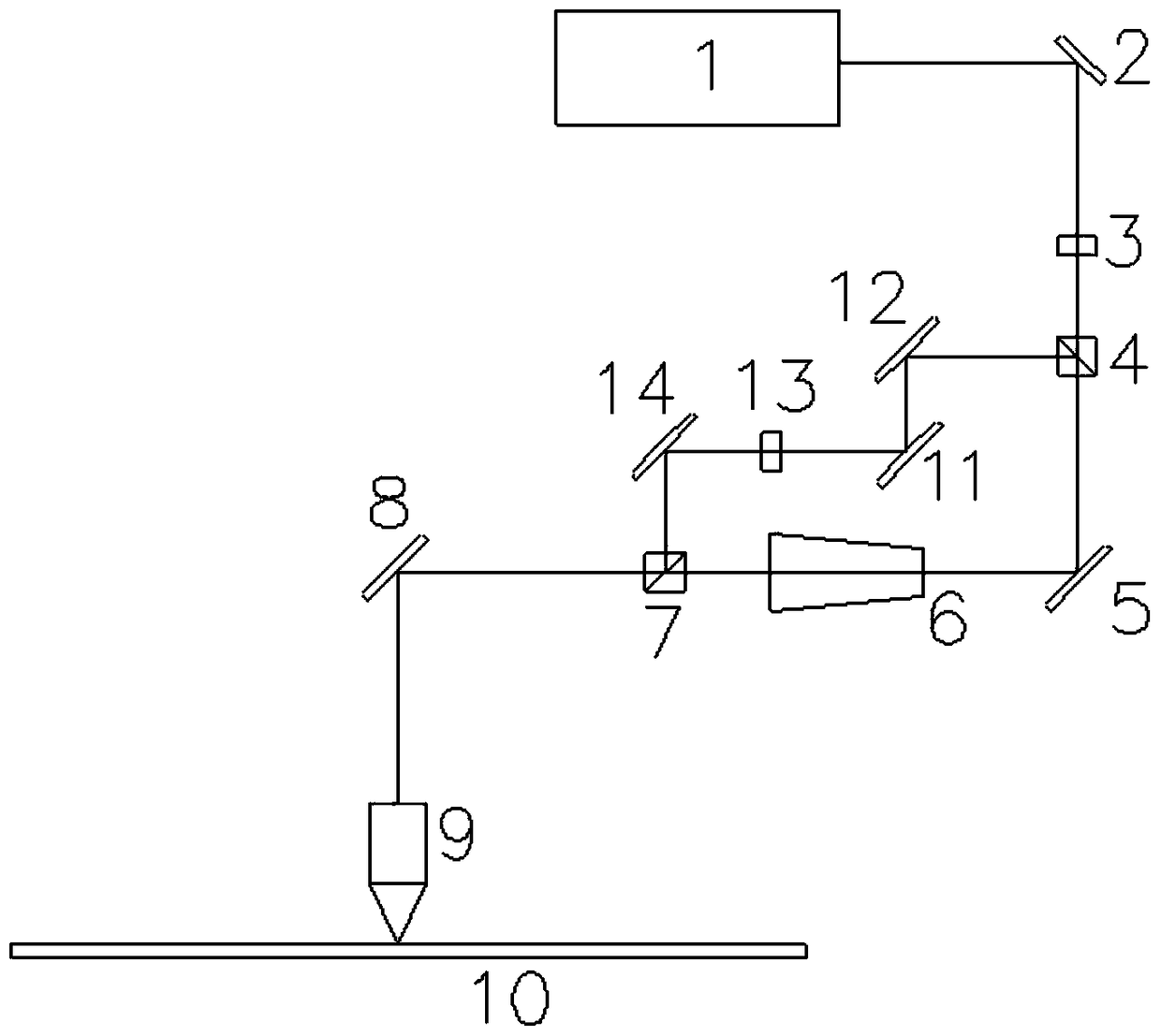
[0031] refer to Figure 3-Figure 4 As shown, the present invention provides a dual-focus laser micromachining device, including a laser 1, a first 45-degree reflector 2, a first half-wave plate 3, a third 45-degree reflector 8 and a focusing mirror 9, which are located at the first The output optical path of the half-wave plate 3 is used to divide the laser beam into the first polarizer 4 of the horizontally polarized beam P and the vertically polarized beam S, and the horizontal optical path device and the vertical optical path device respectively arranged on the horizontal polarized optical path and the vertical polarized optical path , the second polarizer 7 arranged at the output end of the horizontal optical path device and the output end of the vertical optical path device, the horizontally polarized light beam P passes through the horizontal polarized optical path, the second polarizer 7, the third 45-degree mirror 8 and the focusing mirror 9 in sequence Afterwards, the...

Embodiment 2

[0049] refer to image 3 , Figure 4 and Figure 5 As shown, the present embodiment also provides a dual-focus laser micromachining method, comprising the following steps,

[0050] The first step is to place the workpiece 10 under the focusing mirror 9. The workpiece 10 can be selected from glass, LED wafers, silicon wafers, semiconductors, etc.;

[0051] The second step is to turn on the laser 1 to emit a laser beam. The wavelength range of the laser beam is 355nm-1064nm, which can be other lasers such as ultraviolet, green, and infrared;

[0052] In the third step, the laser beam sequentially passes through the first 45-degree mirror 2, the first half-wave plate 3 and the first polarizer 4 to form a horizontally polarized beam P and a vertically polarized beam S;

[0053] Step 4: The horizontally polarized light beam P sequentially passes through the horizontally polarized optical path, the second polarizer 7, the third 45-degree mirror 8 and the focusing mirror 9 to form...


PUM

PropertyMeasurementUnit
wavelengthaaaaaaaaaa

Abstract

The invention relates to the technical field of laser processing, and discloses a dual-focus laser micro-processing device and a processing method thereof. The processing device includes a laser, a first 45-degree reflector, a first half-wave plate, a third 45-degree reflector and a focusing mirror, which are arranged on the output optical path of the first half-wave plate for splitting the laser beam into horizontally polarized beams P and the first polarizer of the vertically polarized light beam S, the horizontal optical path device and the vertical optical path device respectively arranged on the horizontal polarized optical path and the vertical polarized optical path, the second polarizer arranged at the output end of the horizontal optical path device and the output end of the vertical optical path device, horizontal The polarized beam P passes through the horizontal polarized optical path, the second polarizer, the third 45-degree mirror and the focusing mirror in turn to form the first focal point on the workpiece, and the vertically polarized beam S sequentially passes through the vertical polarized optical path, the second polarized sheet, the second Three 45-degree mirrors and a focusing mirror form a second focal point on the workpiece. The invention has the advantages of high processing efficiency and good effect.

Description

technical field [0001] The invention relates to the technical field of laser processing, and more specifically relates to a dual-focus laser micro-processing device and a processing method thereof. Background technique [0002] In laser micro-precision processing industries such as glass, LED wafers, silicon wafers, semiconductors, etc., with the improvement of product grades, the thickness of products tends to become thicker. Simple single focus for multi-round multi-layer processing The method began to lead to a decline in production efficiency, so it is of great significance to improve the efficiency of dual-focus laser precision micromachining. [0003] In many traditional laser micromachining applications, the laser beam passes through the external optical path and enters the focusing lens to focus to form a focus, and the high peak power density of the focus is used to process materials. As the thickness of the material to be processed increases, people pay more and m...

Claims


Application Information

Patent Timeline
Patent Type & Authority Patents(China)
IPC IPC(8): B23K26/064B23K26/067B23K26/50
Inventor 王焱华庄昌辉陈红陈治贤唐建刚尹建刚高云峰
Owner 深圳市大族微加工软件技术有限公司
Why Eureka
Try Eureka