
Pneumatic gripper device

A pneumatic gripper and finger technology, applied in the direction of manipulators, chucks, manufacturing tools, etc., can solve the problems of inaccurate and stable grasping and releasing of workpieces, poor practical performance, cumbersome operation, etc., and achieve accurate and stable grasping and releasing of workpieces , low cost, good sports performance

Inactive Publication Date: 2015-12-23
芜湖陀曼精机科技有限公司
View PDF8 Cites 4 Cited by
  • Summary
  • Abstract
  • Description
  • Claims
  • Application Information

AI Technical Summary

Problems solved by technology

For example, the environment is harsh during hot forging. This operation generally requires flexible, simple, reliable, and high repeatability. At present, many manipulators have been designed to meet this demand. Due to the complex structure, they are not enough in the process of grabbing and releasing workpieces. Accurate and stable, cumbersome operation, poor practical performance

Method used


Image

  • Pneumatic gripper device
  • Pneumatic gripper device

Examples


Embodiment Construction

[0017] The specific implementation manner of the present invention will be described in further detail below by describing the embodiments with reference to the accompanying drawings.

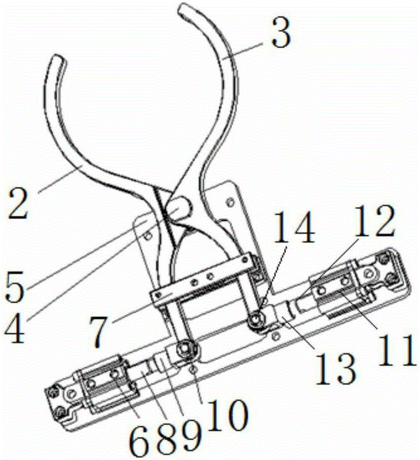
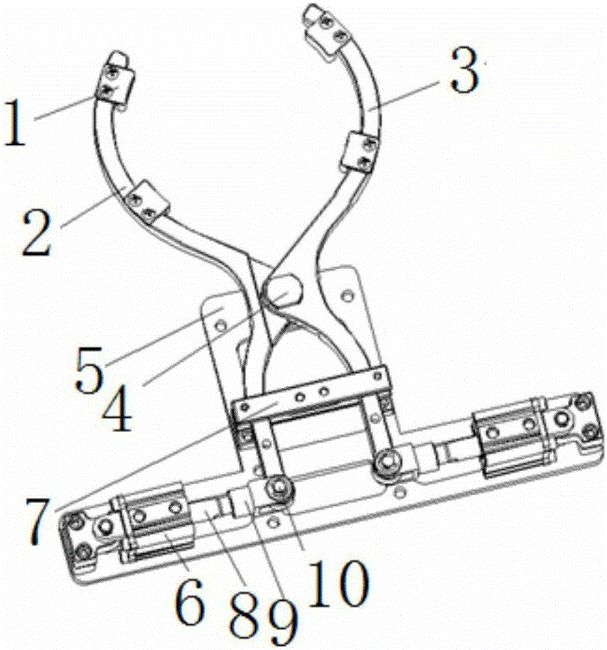
[0018] Such as figure 1 with figure 2 As shown, the pneumatic gripper device includes finger I2, finger II3, finger shaft 4, fixed mounting plate 5, cylinder I6, cylinder II11, and support plate 7, wherein the fixed mounting plate 5 is a T-shaped plate structure, and the finger shaft is set On the raised part of the T-shaped plate structure, the cylinder I and the cylinder II are respectively arranged on the two protruding ends of the T-shaped plate structure.

[0019] The finger I2 and the finger II3 are arranged oppositely, and the finger I and the finger II are hinged through the finger shaft 4 arranged on the fixed mounting plate.

[0020] Cylinder Ⅰ6 and cylinder Ⅱ11 are arranged oppositely, the end of piston rod Ⅰ8 of cylinder Ⅰ is connected with one end of connecting rod Ⅰ9, the other...


PUM


Abstract

The invention discloses a pneumatic gripper device. The pneumatic gripper device comprises a finger I and a finger II corresponding to the finger I. The pneumatic gripper device further comprises a fixed installing plate and air cylinders arranged on the fixed the installing plate. The finger I and the finger II are hinged to each other through a finger rotating shaft arranged on the fixed installing plate. The air cylinders include the air cylinder I and the air cylinder II. A piston rod of the air cylinder I and a piston rod of the air cylinder II are hinged to the same ends of the two fingers. The gripping end of the finger I and the gripping end of the finger II are each provided with an adjusting block. The structure is simple, thrust of the air cylinders is transferred into clamping force, a workpiece can be gripped reliably, the air cylinders are convenient to control, the workpiece can be gripped and released stably, the operation is simple and convenient, the movement performance is good, and the cost is low.

Description

technical field [0001] The invention relates to the technical field of automation equipment, in particular to a pneumatic gripper device. Background technique [0002] With the rapid development of modern industry, production automation has become a prominent theme. In processing, handling, assembly and other industries, many stations are for picking up workpieces. For example, the environment is harsh during hot forging. This operation generally requires flexible, simple, reliable, and high repeatability. At present, many manipulators have been designed to meet this demand. Due to the complex structure, they are not enough in the process of grabbing and releasing workpieces. Accurate and stable, complex operation, poor practical performance. Contents of the invention [0003] Aiming at the deficiencies of the prior art, the technical problem to be solved by the present invention is to provide a pneumatic gripper device, which has a simple structure and is easy to operate...

Claims


Application Information

Patent Timeline
Patent Type & Authority Applications(China)
IPC IPC(8): B25J15/08
Inventor 邵金金蒋立军
Owner 芜湖陀曼精机科技有限公司
Learn More