Variable-rigidity elastic joint of cam structure

An elastic joint and variable stiffness technology, applied in the field of robotics, can solve the problems of complex joint structure, poor variable stiffness characteristics, and large energy consumption of variable stiffness robots, achieving continuous and reliable variable stiffness process, stable variable stiffness process, and easy manufacturing and processing. Effect

Active Publication Date: 2015-12-23
SICHUAN UNIV
View PDF5 Cites 29 Cited by
  • Summary
  • Abstract
  • Description
  • Claims
  • Application Information

AI Technical Summary

Problems solved by technology

However, judging from the many structures designed abroad, there are still many problems in its structure, such as the complex joint st...

Method used


Image

  • Variable-rigidity elastic joint of cam structure
  • Variable-rigidity elastic joint of cam structure
  • Variable-rigidity elastic joint of cam structure

Examples


Embodiment 1

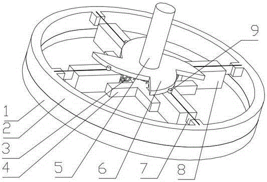
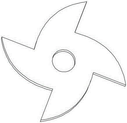
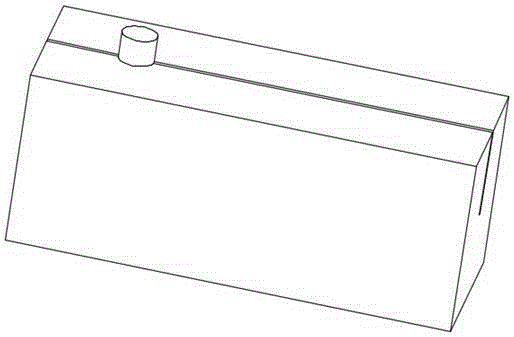
[0037] A variable stiffness elastic joint with a cam structure, consisting of a casing (1), a shaft (5) and an outer ring (2); it is characterized in that the shaft (5) is set at the center of rotation of the casing (1), and is connected to the casing ( 1) are fixedly connected, and the casing (1) and the outer ring (2) are connected by a rotating pair; the outer ring (2) is radially installed with a plurality of symmetrical spring pieces (7), and each spring One end of the piece (7) is fixedly connected to the outer ring (2), and the other end is fixedly connected to the shaft (5) through the spring (3); one end of the spring (3) is connected to the shaft (5), and the other end is connected to the sliding on the block (8); the sliding block (8) is installed in the middle of the spring leaf (7), distributed symmetrically with the spring leaf (7), and is slidingly connected with the spring leaf (7); the shaft (5 ) is installed with a cam disc (6), the cam disc (6) is a centrall...

Embodiment 2

[0042] Such as Figure 12 As shown, the variable stiffness robot elastic joint in this example is installed at the leg joint of the hexapod bionic robot, the input end 12 of the bionic robot leg is fixedly connected with the shell 1 of the elastic joint, and the outer ring 2 is connected to the output end 13 of the bionic robot leg Fixed connection. In the application process, the stiffness characteristics of the elastic joint are set in advance according to the working condition information. During the walking process of the bionic robot, when the motor drives the input end 12 of the leg of the bionic robot to rotate, the external load will affect the output end 13 of the leg of the bionic robot. When an impact occurs, the elastic joint in this example will produce a buffering effect through the elastic action of the spring leaf 7, so that there is an elastic action between the outer ring 2 and the shell 1, which effectively protects the leg joints of the bionic robot and imp...

Embodiment 3

[0044] Such as Figure 13 As shown, the elastic joint of the robot with variable stiffness in this example is installed at the leg joint of the human prosthesis. The elastic joint is installed at the joint between the thigh and the lower leg of the human prosthesis. The input end of the driving lower leg is fixedly connected with the shell 1 of the elastic joint. The ring 2 is fixedly connected to the prosthetic leg 15. During the application process, the stiffness characteristics of the elastic joint are set in advance according to the working condition information. When the prosthesis is walking, when the motor drives the input end of the prosthetic leg 15 to rotate, the external load will affect the prosthesis. The calf 15 produces an impact, and the elastic joint of this example will produce a buffering effect through the elastic action of the spring leaf 7, so that there is an elastic action between the outer ring 2 and the shell 1, effectively protecting the prosthetic le...


PUM


Abstract

The invention discloses a variable-rigidity elastic joint of a cam structure. The variable-rigidity elastic joint is composed of a shell, a shaft and an outer ring. The shaft is arranged at the rotation center of the shell and fixed to the shell. The shell and the outer ring are connected through a rotation pair. A plurality of symmetrical leaf springs are arranged on the outer ring in the radial direction. One end of each leaf spring is fixedly connected with the outer ring, and the other end of each leaf spring penetrates through a spring to be fixedly connected with the shaft. One end of each spring is connected to the shaft, and the other end of each spring is connected to a sliding block. The sliding blocks are arranged in the middles of the leaf springs and connected with the leaf springs in a sliding mode. A cam disk is arranged on the shaft, of a central symmetry structure and connected with the shaft through a rotation pair. A cam roller is arranged at the upper end of each sliding block. Cam transmission is achieved through the cam disk and the cam rollers. The variable-rigidity elastic joint solves the problems that an existing structure is relatively complex and the variable-rigidity characteristic is poor, and the variable-rigidity elastic joint which is simple in structure and allows the rigidity to be regulated in real time in the movement process can be obtained.

Description

technical field [0001] The invention relates to the technical field of robots, in particular to a variable stiffness elastic joint with a cam structure. Background technique [0002] With the rapid development of science and technology, the application of robot technology at this stage is very extensive, especially in the industrial field. At present, with the development of robot technology towards flexibility, the collaborative work of multiple robots and the interaction between robots and humans are becoming more and more common. The emergence of this phenomenon will inevitably increase the requirements for flexible technology and adaptability of robots. This is also a hot spot of domestic and foreign research at this stage. [0003] From the perspective of the entire composition of the robot, the robot joints are the key components for the robot to achieve various movements. Rigid joints and elastic joints are mainly used in the existing robot technology. There are r...

Claims


Application Information

Patent Timeline
IPC IPC(8): B25J17/00
Inventor 高文翔汤卿李超叶北发王袈欢姚进
Owner SICHUAN UNIV
Why Eureka
Try Eureka