A cam structure variable stiffness elastic joint
An elastic joint and variable stiffness technology, applied in the field of robotics, can solve the problems of complex joint structure, poor variable stiffness characteristics, and large energy consumption of variable stiffness robots, and achieve continuous and reliable variable stiffness process, stable variable stiffness process, and easy manufacturing and processing Effect
- Summary
- Abstract
- Description
- Claims
- Application Information
AI Technical Summary
Problems solved by technology
Method used
Image
Examples
Embodiment 1
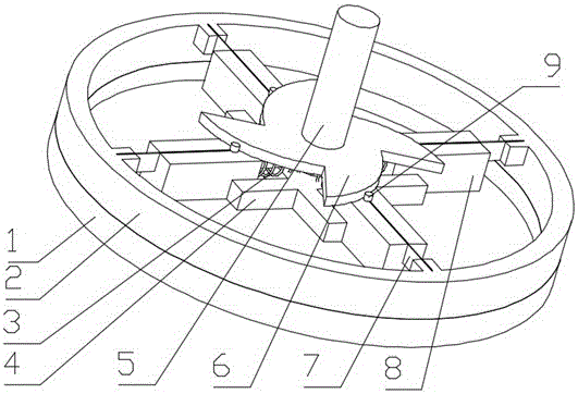
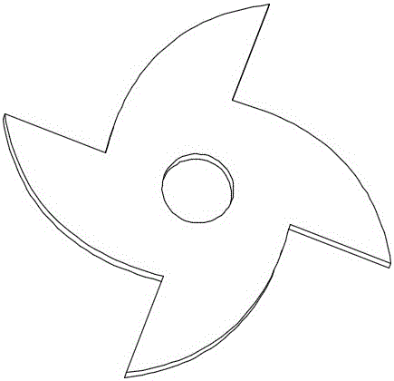
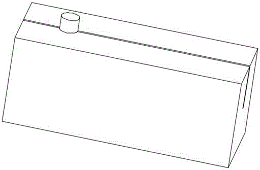
[0037] A cam structure variable stiffness elastic joint is composed of a casing (1), a shaft (5) and an outer ring (2); it is characterized in that the shaft (5) is arranged at the center of rotation of the casing (1), and is connected to the casing ( 1) are fixedly connected, and the housing (1) and the outer ring (2) are connected by a rotating pair; the outer ring (2) is radially installed with a plurality of symmetrical spring pieces (7), and each spring One end of the piece (7) is fixedly connected to the outer ring (2), and the other end is fixedly connected to the shaft (5) through the spring (3); one end of the spring (3) is connected to the shaft (5), and the other end is connected to the sliding on the block (8); the sliding block (8) is installed in the middle of the leaf spring (7), distributed symmetrically with the leaf spring (7), and is slidingly connected with the leaf spring (7); the shaft (5 ) is equipped with a cam disc (6), the cam disc (6) is a center sym...
Embodiment 2
[0042] Such as Figure 12 As shown, a cam structure variable stiffness elastic joint of this example is installed at the leg joint of the hexapod bionic robot, the input end 12 of the bionic robot leg is fixedly connected with the shell 1 of the elastic joint, and the outer ring 2 is connected with the leg of the bionic robot The output terminal 13 is permanently connected. In the application process, the stiffness characteristics of the elastic joint are set in advance according to the working condition information. During the walking process of the bionic robot, when the motor drives the input end 12 of the leg of the bionic robot to rotate, the external load will affect the output end 13 of the leg of the bionic robot. When an impact occurs, the elastic joint in this example will produce a buffering effect through the elastic action of the spring leaf 7, so that there is an elastic action between the outer ring 2 and the shell 1, which effectively protects the leg joints of...
Embodiment 3
[0044] Such as Figure 13 As shown, a cam structure variable stiffness elastic joint in this example is installed at the leg joint of the human prosthesis, and an elastic joint is installed at the joint between the thigh and the calf of the human prosthesis, and the input end of the driving calf is fixed to the shell 1 of the elastic joint Connection, the outer ring 2 is fixedly connected with the prosthetic calf 15. During the application process, the stiffness characteristics of the elastic joint are set in advance according to the working condition information. During the prosthetic walking process, when the motor drives the input end of the prosthetic calf 15 to rotate, the external load It will have an impact on the prosthetic calf 15, and the elastic joint in this example will have a buffering effect through the elastic action of the spring leaf 7, so that there is an elastic action between the outer ring 2 and the shell 1, which effectively protects the joints of the pro...
PUM
 Abstract
Description
Claims
Application Information
 - R&D
- Intellectual Property
- Life Sciences
- Materials
- Tech Scout
- Unparalleled Data Quality
- Higher Quality Content
- 60% Fewer Hallucinations
Browse by: Latest US Patents, China's latest patents, Technical Efficacy Thesaurus, Application Domain, Technology Topic, Popular Technical Reports.
© 2025 PatSnap. All rights reserved.Legal|Privacy policy|Modern Slavery Act Transparency Statement|Sitemap|About US| Contact US: help@patsnap.com


