
A flexible foot system for a multi-legged robot that can detect contact between feet and the ground

A multi-legged robot and flexible foot technology, applied in the field of robotics, can solve the problems of difficult selection of spring stiffness, low reliability, poor shock absorption performance, etc., and achieve the effect of compact structure, good sensitivity and small volume

Active Publication Date: 2017-09-26
BEIHANG UNIV
View PDF9 Cites 0 Cited by
  • Summary
  • Abstract
  • Description
  • Claims
  • Application Information

AI Technical Summary

Problems solved by technology

The spherical structure of the foot system has a simple structure and a wide range of applications, but it has the disadvantages of difficult selection of spring stiffness, low precision, low reliability, and poor shock absorption performance.
Real-time detection of the contact between the robot foot and the ground is the key to realize the multi-legged walking robot walking in a complex environment, but the existing robot foot structure can not meet the needs of practical applications, so a reliable multi-legged walking robot foot is designed. The end system is of great significance and needs further research

Method used


Image

  • A flexible foot system for a multi-legged robot that can detect contact between feet and the ground
  • A flexible foot system for a multi-legged robot that can detect contact between feet and the ground
  • A flexible foot system for a multi-legged robot that can detect contact between feet and the ground

Examples


Embodiment Construction

[0021] The present invention will be described in further detail below in conjunction with the accompanying drawings.

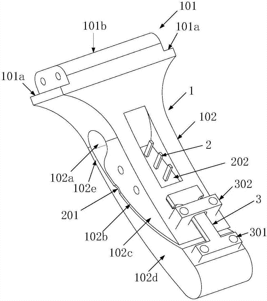
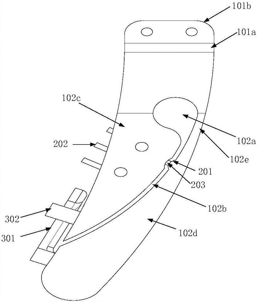
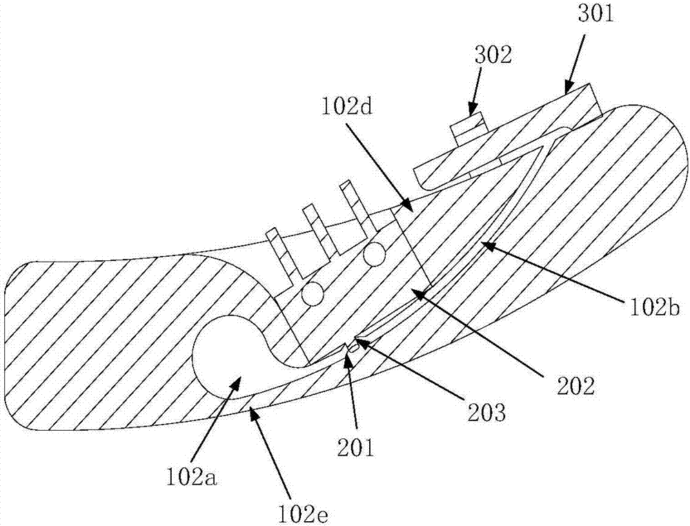
[0022] The multi-legged robot flexible foot system of the present invention includes a flexible foot 1 and a contact detection mechanism 2 and a limit mechanism 3 installed on the flexible foot 1 .

[0023] The flexible foot 1 is integrally formed by 3D printing, including a calf connection part 101 and a flexible joint part 102 . Among them, the lower leg connection part 101 is used to realize the connection between the flexible foot system of the multi-legged robot of the present invention and the robot lower leg, and is suitable for connection with different robot lower legs. The inner side and the outer side of the lower leg connection part 101 have boss positioning surfaces 101a, and the upper end of the middle part has a protruding part 101b, and the protruding part 101b is provided with mounting screw holes along the left and right directions. Thus, w...


PUM


Abstract

The invention discloses a multi-foot robot flexible foot system capable of detecting the contact condition between a foot and the ground. The multi-foot robot flexible foot system comprises the flexible foot and a contact detecting mechanism. The top end of the flexible foot is used for being connected with the shank of a robot. A flexible joint part is arranged on the lower portion of the flexible foot. The lower end of the flexible joint part is a landing end. A flexible joint is divided into an inner side part and an outer side part. The upper portion of the outer side part is a thin wall. A movable contact is designed on the outer side part. A micro switch is installed on the inner side part. The micro switch and the movable contact jointly form the contact detecting mechanism. When the landing end of the outer side part bears force, the outer side part gets close to the inner side part, a contact of the micro switch is pressed down through the movable contact, and it is detected that the flexible foot makes contact with the ground at the moment. When the landing end of the outer side part does not bear force, the movable contact makes contact with the contact of the micro switch, but the movable contact does not bear force, and it is detected that the flexible foot does not make contact with the ground at the moment. The multi-foot robot flexible foot system has the beneficial effects of being high in reliability, good in sensitivity, compact in structure, small in size and light in weight.

Description

technical field [0001] The invention belongs to the technical field of robots, and in particular relates to a flexible foot system of a multi-legged robot capable of detecting the contact between feet and the ground. Background technique [0002] The multi-legged walking robot does not need a continuous support surface during the movement, so it has better environmental adaptability and movement flexibility than wheeled and tracked robots. In practical applications, the working environment of a multi-legged walking robot is extremely complex. In order to realize the real-time estimation of the robot's own attitude and the online planning of the gait, the robot needs to obtain the contact information between the feet and the ground in real time. [0003] The feet of traditional walking robots mostly use flat or spherical structure feet. For example: the invention patent with application number 201310043348.4 "A humanoid robot foot structure based on modular array sensors" an...

Claims


Application Information

Patent Timeline
Patent Type & Authority Patents(China)
IPC IPC(8): B25J19/00B25J19/02
CPCB25J19/00B25J19/02
Inventor 丁希仑杨帆尹业成彭赛金
Owner BEIHANG UNIV
Learn More