Forming mould for composite-material fan blade of aero-engine

An aero-engine and composite material technology, which is applied in the field of structural design and manufacturing of aeronautical technology equipment, can solve problems such as difficult processing of aero-engine composite material fan blades, and achieve the effects of simple structure, convenient disassembly and assembly, and reduced production costs

Active Publication Date: 2015-12-23
陕西道博新材科技有限公司
View PDF6 Cites 7 Cited by
  • Summary
  • Abstract
  • Description
  • Claims
  • Application Information

AI Technical Summary

Problems solved by technology

Moreover, carbon fiber reinforced resin-based composite materials are difficult to process materials, and the existing CNC machining technology is difficult to process fan blades that meet the requirements of aero-engine composite materials; It is of great significance in the development of a new generation of high thrust-to-weight ratio aeroengines to produce a carbon fiber reinforced resin matrix composite fan blade mold that meets the requirements to improve production efficiency and reduce production costs

Method used


Image

  • Forming mould for composite-material fan blade of aero-engine
  • Forming mould for composite-material fan blade of aero-engine

Examples


Embodiment Construction

[0019] This embodiment is a composite material fan blade molding die for an aero-engine.

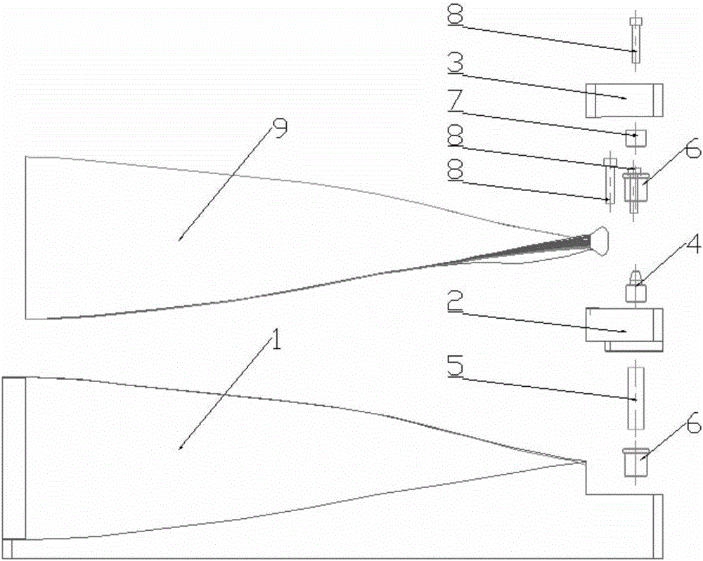
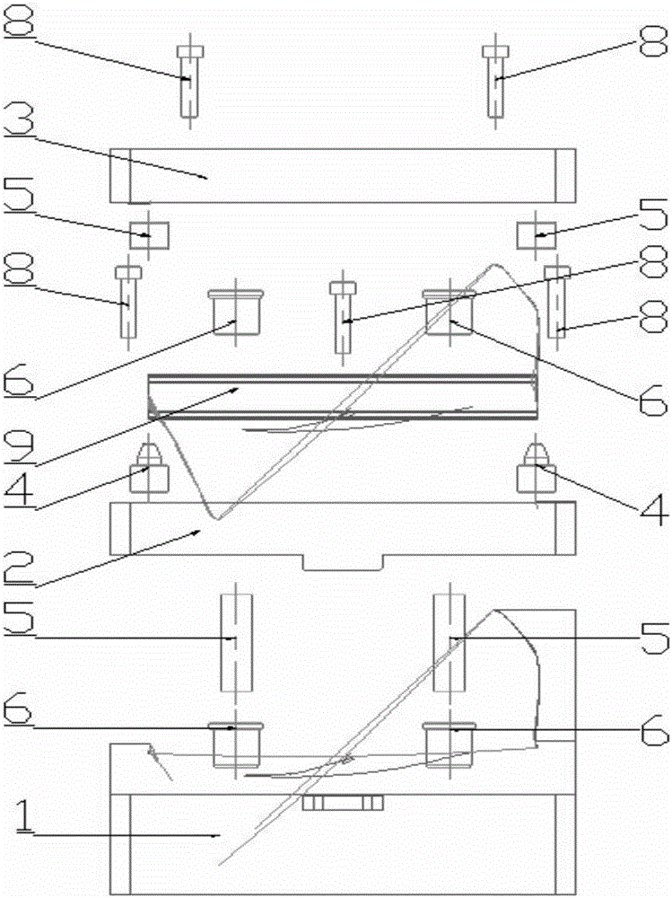
[0020] refer to figure 1 , figure 2 , The composite material fan blade molding mold for aero-engine consists of blade body mold 1, mortise lower mold 2, mortise upper mold 3, conical positioning pin 4, positioning pin 5, flanging bush 6, bushing 7, bolt 8 and blade 9 components; the aero-engine composite fan blade forming mold has two parts: an open mold and a closed mold, wherein the airfoil mold 1 is an open mold, and the mortise lower mold 2 and the mortise upper mold 3 are closed molds.

[0021] The surface of the airfoil mold 1 takes the direction from the blade root to the blade tip as the axis to form a complex free-form surface with a thickness in the middle and thin sides on both sides. The middle part of the protruding section at the end of the airfoil mold 1 has a groove for the tenon root lower mold 2 to limit the position. The flanging bush 6 is embedded in the protruding...


PUM


Abstract

The invention discloses a forming mould for a composite-material fan blade of an aero-engine. A blade body mould of the forming mould is an open mould; and a tenon root lower mould and a tenon root upper mould are closed moulds. A complex free curved surface which is thick in middle and thin in two sides is formed on the surface of the blade body mould by taking a direction from the blade tenon root to the blade tip as an axis; a groove for limiting the tenon root lower mould is formed in the middle of a convex section at the tail end of the blade body mould; a lug boss which is matched with the groove in the tail end of the blade body mould is arranged on the lower end surface of the tenon root lower mould; the tenon root lower mould and the blade body mould are limited and fixedly connected by flanging lining sleeves, dowel pins and bolts which are symmetrical distributed; and the tenon root upper mould and the tenon root lower mould are limited and fixedly connected by virtue of a lining sleeve, a tapered dowel pin and a bolt. The blade body mould, the tenon root lower mould and the tenon root upper mould are coaxially mounted. The forming mould is simple in structure and convenient in dismounting, and capable of being repeatedly used for many times while the production precision of the forming mould is not affected. The forming mould for the composite-material fan blade of the aero-engine not only can improve the processing efficiency of the composite-material fan blade, but also can reduce the production cost of the composite-material fan blade.

Description

technical field [0001] The invention relates to the technical field of structural design and manufacture of aeronautical technology equipment, in particular to a metal mold for precision manufacturing of composite material fan blades of aero-engines. Background technique [0002] In the aviation industry, the widely used engines are mainly turbofan engines. Engine blades are thin-walled structural parts with complex free-form surfaces, and the design requires high precision and light weight. Especially when the fourth-generation aero-engine requires a higher thrust-to-weight ratio, traditional metal materials are far from being able to meet its requirements, and even lightweight metal materials such as titanium alloys have been unable to do what they want. Therefore, there is an urgent need for a lighter material with good physical and chemical properties to replace the existing materials. The increasing maturity of carbon fiber reinforced resin matrix composites has broug...

Claims


Application Information

Patent Timeline
Patent Type & Authority Applications(China)
IPC IPC(8): B29C70/34B29C70/54B29C33/00
CPCB29C33/00B29C70/342B29C70/54
Inventor 刘维伟周建武吴道生陆人杰陈琳琳
Owner 陕西道博新材科技有限公司
Why Eureka
Try Eureka