
Eureka
For R&D, Eureka makes reading and utilizing patents & technical documents easy.
Eureka AIR
Designed for self-driven R&D workflows. Generate viable solutions, solve complex R&D challenges, empower your innovation with AI.

Eureka Materials
Designed for material experts only. Revolutionize your material R&D, from search, analyze, to developing new materials.

TechResearch
Generate reliable direction feasibility study reports for your R&D in just a few steps.

TechSeek
Discover and master advanced knowledge NOW. Basics, ideas, possibilities, all at once.

TechMind
As an expert in R&D Theories, TechMind can generates customized viable solutions instantly.

TechRisk
Analyze your overall solution with one click, know your potential R&D risks in advance.

TechMonitor
Get weekly tech updates, stay abreast of the latest tech innovations and key insights.
Packing machine capable of achieving continuous feeding
A baler and feeding technology, which is applied in the field of balers, can solve the problems that balers cannot be compressed, occupy a large turnover space, and are difficult to recycle, and achieve the effect of increasing the single loading capacity
- Summary
- Abstract
- Description
- Claims
- Application Information
AI Technical Summary
Problems solved by technology
Method used
Image

Examples
Embodiment 1
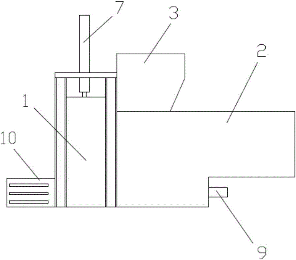
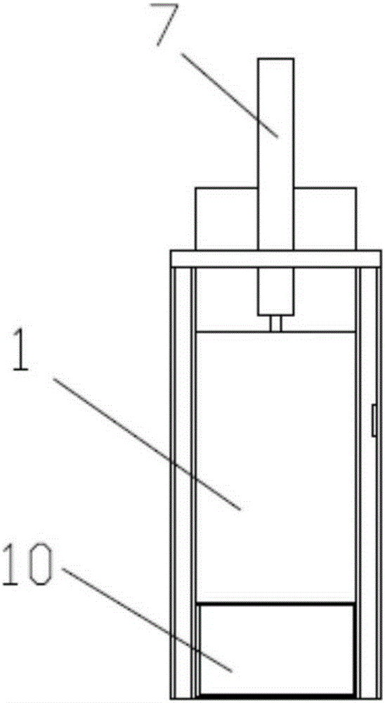
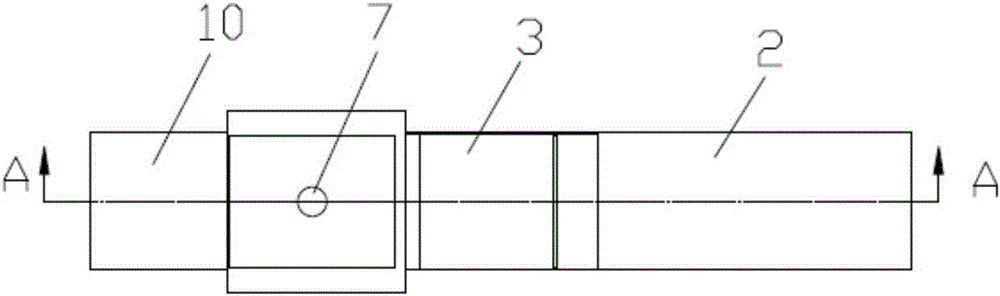
[0037] see Figure 1 to Figure 5 , The baler capable of continuous feeding of the present invention includes a compression chamber 1 and a compression mechanism, and the compression mechanism includes a first-stage compression mechanism and a second-stage compression mechanism. in:
[0038] One of the sides of the compression chamber 1 is connected with a horizontal low-pressure feeding channel 2, and this side of the compression chamber 1 is provided with a feed inlet 1-1 communicated with the horizontal low-pressure feeding channel 2, and the lateral low-pressure feeding channel 2 The upper part is provided with a feeding port 3; the first-stage compression mechanism includes a feeding push plate 4 and a feeding power mechanism 5 that drives the feeding push plate 4 to perform lateral reciprocating motion, and the feeding push plate 4 is arranged at a horizontal low pressure In the feeding channel 2, a material baffle 15 is provided on the upper part of the feeding push plat...
Embodiment 2
[0050] see Figure 11 , compared with embodiment 1, this embodiment differs in that:
[0051] In this embodiment, the bag ejection mechanism is composed of a first-stage compression mechanism, the lower edge of the feeding push plate 4 is flush with the bottom surface of the compression chamber 1, and the discharge port 1-2 is facing the feeding Push plate 4 settings. In this way, the first-stage compression mechanism simultaneously has the functions of feeding and pushing out the bag, thereby simplifying the structure.
[0052] When working, after the first-stage compression mechanism completes a cycle of feeding action and the second compression mechanism completes one compression, the feeding power mechanism 5 in the first-stage compression mechanism makes a further extension movement forward to pass the feeding The push plate 4 pushes out the material bag 16, so that the same mechanism has two functions and improves the power consumption efficiency.
Embodiment 3
[0054] see Figure 12 The difference between this embodiment and Embodiment 1 is that in this embodiment, a blocking door 17 is provided in the discharge port 1-2, and a driving blocking door 17 is connected to the blocking door 17 for vertically upward The opening and closing control mechanism 18 of downward movement, this opening and closing control mechanism 18 is made of pneumatic cylinder or hydraulic cylinder. By setting the blocking door 17, the discharge port 1-2 can be effectively blocked during the feeding stage and the compression stage, and the compression effect can be improved.
PUM
 Abstract
Description
Claims
Application Information
 - R&D Engineer
- R&D Manager
- IP Professional
- Industry Leading Data Capabilities
- Powerful AI technology
- Patent DNA Extraction
Browse by: Latest US Patents, China's latest patents, Technical Efficacy Thesaurus, Application Domain, Technology Topic, Popular Technical Reports.
© 2024 PatSnap. All rights reserved.Legal|Privacy policy|Modern Slavery Act Transparency Statement|Sitemap|About US| Contact US: help@patsnap.com