

Automatic seal machine
A seal machine, automatic technology, applied in printing, stamping, etc., can solve the problems of large volume, large mechanism volume, complex structure design and operation process, etc., to achieve the realization of chapter changing operation, stamp pressing operation and good market value Effect
- Summary
- Abstract
- Description
- Claims
- Application Information
AI Technical Summary
Problems solved by technology
Method used
Image

Examples
Embodiment 1
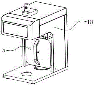
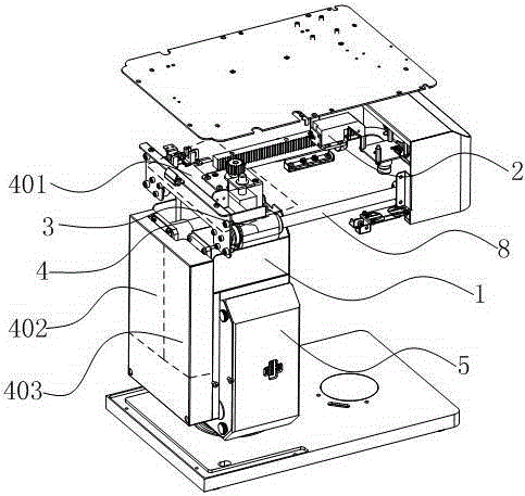
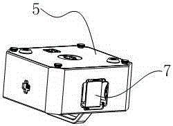
[0048] The present embodiment proposes a kind of automatic seal machine, and this automatic seal machine comprises core 1 and frame 2, and core 1 and frame 2 are provided with such as figure 1 Shown in enclosure 18, the figure 2 In the shown structure, the movement 1 is suspended on the sliding shaft 8 of the frame 2 through the linear bearing 3, the movement 1 is provided with the movement power part 4 and the stamp box 5, and the stamp box 5 is provided with a stamp turntable module 6, The stamp turntable module 6 includes a stamp assembly 601 for stamping; the movement power part 4 includes a displacement driver 401 that drives the core 1 to move along the slide shaft 8, a stamp driver 402 that drives the stamp assembly 601 to move, and drives the stamp The chapter changing driver 403 that the turntable module 6 rotates, such as figure 2 The part shown in the dashed box. On the stamp box 5, there are such image 3 Press window 7 as shown.
Embodiment 2
[0050] The difference between this embodiment and embodiment 1 is: as Figure 4 As shown, the seal turntable module 6 involved in this embodiment is a turntable structure with a card slot 602. The top of the turntable structure is provided with two layers of power-driven adapter shafts inside and outside, and the inner layer is connected to the stamp assembly 601 and The seal driving adapter shaft 603 of the seal driving part 402, the outer side is the chapter changing driving connecting shaft 604 connected to the chapter changing driving part 403; The seal sleeve 606 and the return spring 607 for placing the seal; the stamp assembly 601 acts on the seal sleeve 606 .
[0051] In this example, if Figure 5 As shown, the stamp box 5 is a box structure composed of a stamp box bottom shell 501 and a stamp box loam cake 502. The stamp turntable module 6 is arranged in the box body structure, and the stamping window 7 is arranged on the stamp box bottom shell 501. The closed manag...
Embodiment 3
[0053] The difference between this embodiment and embodiment 2 is: as Figure 6 As shown, in this embodiment, the displacement driving member 401 includes front and rear motors 4012 provided with gears 4011 , the front and rear motors 4012 are arranged on the movement 1 , and the rack 9 matching the gears 4011 is also provided on the frame 2 .
[0054] The bottom of the movement 1 is provided with a base 10, and the base 10 is provided with a printing pad 11 and a seal pad 12; the movement 1 is provided with a sensor 13, which is set as Figure 6 The two groups of sensors 13 shown correspond to the two groups of sensors 13. The frame 2 is provided with two groups of sensor shielding sheets 14 that control the movement limit of the core 1. position, the stamping window 7 corresponds to the printing pad 11; when the sensor 13 moves with the core 1 to the mating position of another set of sensor shielding sheets 14, the stamping window 7 corresponds to the stamping pad 12.
[00...
PUM
 Abstract
Description
Claims
Application Information