

Dropping device for rotor craft
A technology for a rotorcraft and a delivery device, which is applied to launch devices, aircraft parts, transportation and packaging, etc., can solve the problems of incapable of time-sharing, small loading, and low precision, and achieve good safety, improve efficiency, and reduce costs. Effect
- Summary
- Abstract
- Description
- Claims
- Application Information
AI Technical Summary
Problems solved by technology
Method used
Image

Examples
Embodiment Construction
[0018] The present invention will be further described below in conjunction with the accompanying drawings and specific embodiments.
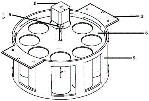
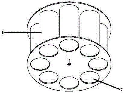
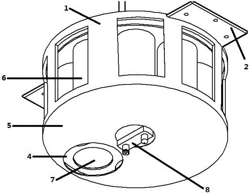
[0019] See attached Figure 1-5 , a delivery device for rotorcraft, including a delivery bin body 1, a fixed bracket 2, a motor 3, and an object delivery hole 4, the delivery bin body 1 includes a casing 5 and an inner turntable 6, the inner turntable includes a loading hole 7, and on the casing 5 A sight 8 is installed, and the sight 8 is made of a camera and a laser generator. The shell 5 is cylindrical as a whole, and the fixing bracket 2 stretches out from both sides of the shell and punches holes. The fixing bracket is installed on the aircraft chassis by screws. Keep relatively still during work, the outer shell 5 and the inner turntable 6 are connected by a rotating shaft and a bearing, so that the outer shell 5 and the inner turntable 6 are kept concentric, and a throwing hole 4 is distributed on the lower part of the shell 5, and the h...
PUM
 Abstract
Description
Claims
Application Information