A blast furnace coal injection system and its control method

A technology of blast furnace coal injection and coal injection tank, which is applied to blast furnaces, blast furnace details, blast furnace parts, etc., can solve the problems of blast furnace stability and unfavorable movement, outlet pressure fluctuations, and the complexity of gas-solid two-phase flow, etc. The effect of tank fluctuation time and improvement of injection accuracy

Active Publication Date: 2018-12-25
CISDI ENG CO LTD +1
View PDF3 Cites 0 Cited by
  • Summary
  • Abstract
  • Description
  • Claims
  • Application Information

AI Technical Summary

Problems solved by technology

This process system is simple, the control method is reliable, and the gas volume control is precise. However, due to the complexity and variability of the gas-solid two-phase flow, the coal volume control has shortcomings such as insufficient accuracy and large hysteresis.
[0003] Due to inaccurate weighing or difficulty in controlling the fluidization state in the blowing tank when changing the blowing tank, it is easy to cause a sudden change in the amount of coal injection, failure to overlap the coal flow, and fluctuations in the outlet pressure during the tank change. Blast furnace temperature fluctuations affect furnace conditions and molten iron quality
At present, the fluctuating time of tank change in the injection system of most steel enterprises accounts for about 10% of the entire injection process, which is very unfavorable to the stability and smooth operation of the blast furnace

Method used


Image

  • A blast furnace coal injection system and its control method
  • A blast furnace coal injection system and its control method
  • A blast furnace coal injection system and its control method

Examples


Embodiment Construction

[0032] The implementation of the present invention will be illustrated by specific specific examples below, and those skilled in the art can easily understand other advantages and effects of the present invention from the contents disclosed in this specification.

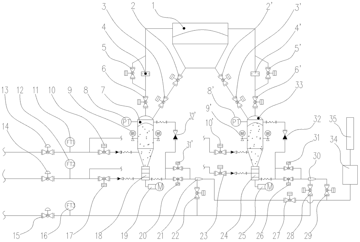
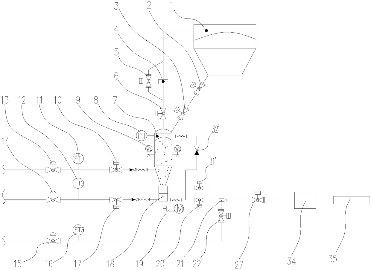
[0033] Such as figure 1 As shown, a blast furnace coal injection system includes pulverized coal bunker 1, 1# injection tank 7, 2# injection tank 33, 1# air replenisher 21, 2# air replenisher 30, distributor through pipelines 34 and spray gun 35, the bottom of described 1# injection tank 7 and 2# injection tank 33 are respectively provided with 1# quantitative feeder 18 and 2# quantitative feeder 24, 1# quantitative feeder 18 and 2 # Quantitative feeder 24 outlets are respectively connected to the first pulverized coal main pipe and the second pulverized coal main pipe, and the first pulverized coal main pipe is provided with 1# injection tank coal outlet valve 20, 1# air supply device 21 and 1# spray tank in sequen...


PUM


Abstract

The invention provides a blast furnace coal injection system. The blast furnace coal injection system comprises an injection tank, a distributor, an injection gun and a coal powder bin communicated through pipes, wherein a quantitative feeder is arranged at the bottom of the injection tank; a coal powder main pipe is arranged between an outlet of the quantitative feeder and the distributor and the injection gun, and is provided with a coal outlet valve and a coal conveying valve; and a pressure homogenizing pipe is arranged between the coal powder main pipe and the top of the injection tank. An air source main pipe is divided into three pipes of pressure stabilization, injection and air replenishment, which are respectively connected with the injection tank, the quantitative feeder and the coal powder main pipe. A control method of the blast furnace coal injection system is as follows: while one injection tank injects, the other injection tank performs preparations of pressure relief, quick relief, powder loading, pressurization and waiting; after the injection of the first injection tank is finished, the tank is replaced; and then, the second injection tank enters the preparation process for alternate circulation. The quantitative feeder is mounted at the bottom of the injection tank, so that the injection precision is improved, the tank replacement fluctuation time is shortened, and necessary conditions are provided for stabilization of blast furnace production.

Description

technical field [0001] The invention belongs to the technical field of blast furnace ironmaking coal injection, and in particular relates to a blast furnace coal injection system and a control method thereof. Background technique [0002] Usually, in actual engineering design, the injection system generally adopts two-tank or three-tank side-by-side injection technology, and the control method for the instantaneous coal injection volume during the injection process mainly adopts the principle of "coarse adjustment of tank pressure and fine adjustment of gas volume". The amount of coal injection is calculated by blowing the weight difference of the injection tank within a certain period of time. This process system is simple, the control method is reliable, and the gas volume control is precise. However, due to the complexity and variability of the gas-solid two-phase flow, the coal volume control has shortcomings such as insufficient accuracy and large hysteresis. [0003] ...

Claims


Application Information

Patent Timeline
Patent Type & Authority Patents(China)
IPC IPC(8): C21B5/00C21B7/00
Inventor 颜新何海熙王贤张杰邹忠平王劲松
Owner CISDI ENG CO LTD
Why Eureka
Try Eureka