Open-end Spinning Device With An Intermediate Chamber

An air-flow type, intermediate cavity technology, applied in the direction of continuous winding spinning machine, spinning machine, open-end spinning machine, etc., can solve problems such as failure of bearings and drives

Active Publication Date: 2015-12-23
MASCHINENFABRIK RIETER AG
View PDF6 Cites 6 Cited by
  • Summary
  • Abstract
  • Description
  • Claims
  • Application Information

AI Technical Summary

Problems solved by technology

If these dirt enters the individual drive and bearing of the spinning rotor at this time, it will cause the bearing and drive to fail

Method used


Image

  • Open-end Spinning Device With An Intermediate Chamber
  • Open-end Spinning Device With An Intermediate Chamber
  • Open-end Spinning Device With An Intermediate Chamber

Examples


Embodiment Construction

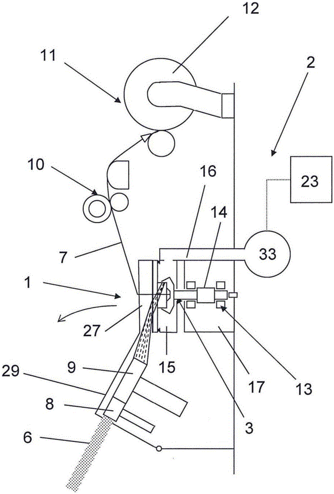
[0033] figure 1 A schematic view of an air spinning device 1 of a rotor spinning machine 2 is shown in a schematic side view. Rotor spinning machine 2 comprises feed device 8 in usual manner, and this feed device is passed loose device 9 ( The unraveling device) conveys the fiber material 6 into the air spinning device 1, and the loosening device 9 loosens the fiber material into individual fibers. In the air spinning device 1, the fiber material 6 is in the rotor cup of the spinning rotor 3 (see Figure 2-6 ) is spun into a yarn 7 and unwound by an unwinding device 10 and wound on a bobbin 12 by means of a winding device 11 .

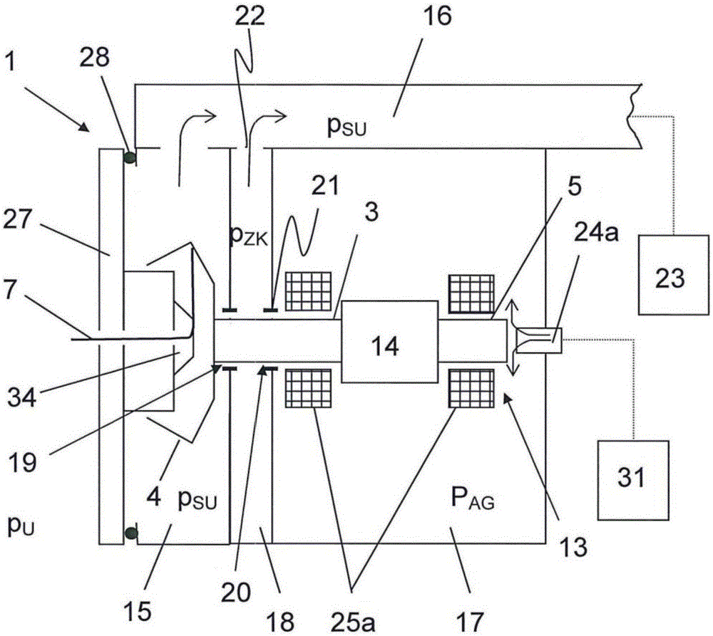
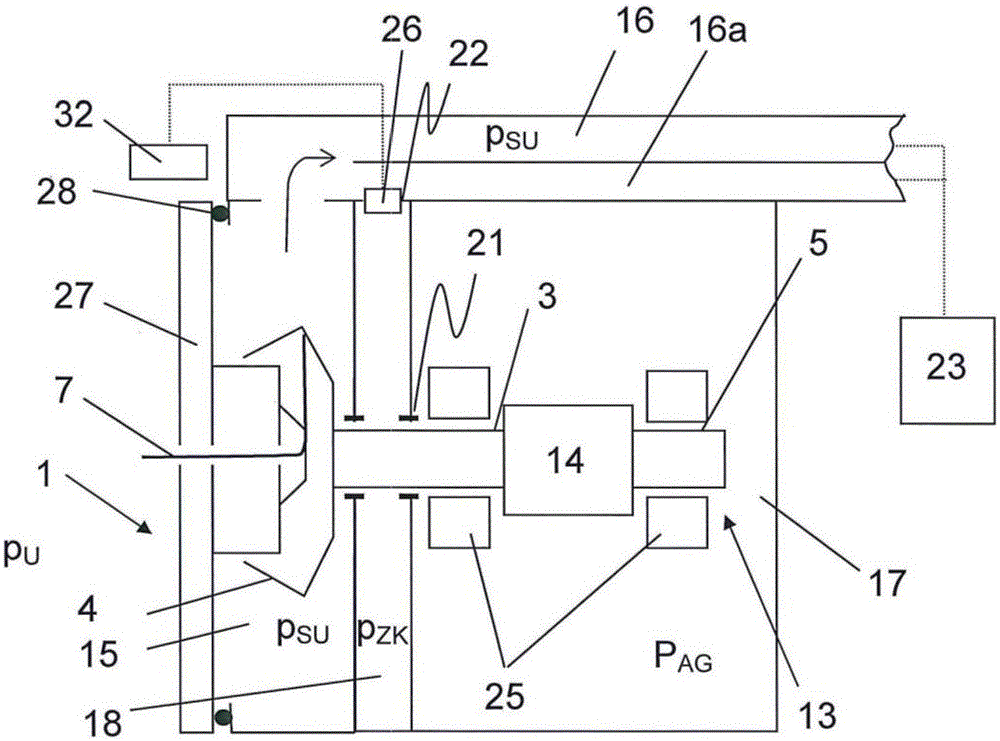
[0034] In addition to the spinning rotor 3 with rotor cup 4 and rotor rod 5 (see Figure 2-6 ), the pneumatic spinning device 1 also includes a rotor housing 15 and a driver housing 17, the rotor cup 4 is arranged in the rotor housing 15, and the rod 5 of the spinning rotor 3 extends in the driver housing 17. According to the present illustration,...


PUM


Abstract

In an open-end spinning device (1) of a rotor spinning machine (2) having a spinning rotor (3) with a rotor cup (4), in which fiber material (6) can be spun, and with a rotor shaft (5) through which the spinning rotor (1) can be driven, and a bearing (13) preferably arranged in a contactless way, with a drive, especially an individual drive (14), to drive the spinning rotor (3), with a rotor housing (15), in which the rotor cup (4) of the spinning rotor (3) is arranged and which is impinged with spinning negative pressure (pSU) during spinning operation through a negative pressure channel (16) of the open-end spinning device (1), and with a drive housing (17), in which the rotor shaft of the spinning rotor extends, and in which the drive and the bearing (13) of the spinning rotors are arranged, the rotor housing (15) and the drive housing (17); are arranged spaced apart from one another in the open-end spinning device (1) in axial direction of the rotor shaft (5). In a corresponding method to operate such an open-end spinning device (1) of a rotor spinning machine (2), the rotor housing (15) is impinged with spinning negative pressure (pSU) during the spinning operation. Air current is prevented from flowing from the rotor housing (15) into the drive housing (17) by arranging the rotor housing (15) and the drive housing (17) spaced apart from one another in the open-end spinning device (1) in an axial direction of the rotor shaft (5).

Description

technical field [0001] The invention relates to an air spinning device of a rotor spinning machine having a spinning rotor with a rotor cup and a rotor rod in which fiber material can be spun into a yarn, the rotor The rod can drive the spinning rotor and is mounted preferably contactlessly in bearings. Furthermore, the pneumatic spinning device has a drive for driving the spinning rotor and a rotor housing in which the rotor cup of the spinning rotor is arranged and which during the spinning The low pressure channel of the station is loaded with spinning low pressure. Furthermore, the pneumatic spinning device has a drive housing in which the rotor rod of the spinning rotor extends and in which the drive and the bearings of the spinning rotor are arranged. Background technique [0002] For supporting pneumatic spinning rotors, besides bearings in wedge-shaped gaps, bearings without contact with the support plate are known, for example magnetic bearings and pneumatic beari...

Claims


Application Information

Patent Timeline
Patent Type & Authority Applications(China)
IPC IPC(8): D01H4/12
CPCD01H4/12D01H4/14D01H11/005
Inventor M·布尔歇特J·舍默尔
Owner MASCHINENFABRIK RIETER AG
Why Eureka
Try Eureka