
The installation method of the spun yarn broken detection control circuit board on the angle steel

A technology for controlling circuit boards and yarn break detection, which is applied in textiles and papermaking, can solve problems such as complicated wiring and difficult installation, and achieves the effects of easy processing, convenient installation and disassembly, and low installation and maintenance costs

Active Publication Date: 2019-03-15
JIANGNAN UNIV
View PDF6 Cites 0 Cited by
  • Summary
  • Abstract
  • Description
  • Claims
  • Application Information

AI Technical Summary

Problems solved by technology

[0005] The present invention aims at the outstanding problem of difficulty in installation due to various reasons such as the large number of circuit boards of the spun yarn breakage detection system and complicated wiring, etc., and proposes a method for installing the spun yarn breakage detection control circuit board on the angle steel

Method used


Image

  • The installation method of the spun yarn broken detection control circuit board on the angle steel
  • The installation method of the spun yarn broken detection control circuit board on the angle steel
  • The installation method of the spun yarn broken detection control circuit board on the angle steel

Examples


Embodiment 1

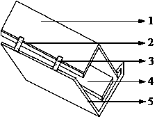
[0024] Such as figure 1 Shown includes fender angle steel 1 , control circuit board angle steel 5 and broken yarn detection control circuit board 4 . The angle steel of the control circuit board is installed under the angle steel of the fender plate, and the two bayonets 3 on one side of the angle steel of the control circuit board are stuck on one side with a convex edge 2 of the angle steel of the fender plate, and are fixed on the angle steel of the fender plate by elastic force. The two form a rectangular space, and the yarn break detection control circuit board is installed in the above-mentioned rectangular space. Such as figure 2 As shown, there is a rectangular hole 7 on one side 6 of the angle steel of the detection control circuit board, which is used for wiring of the yarn breakage detection control circuit board. The other side 9 has a stud hole 8 for installing a broken yarn detection control circuit board. Such as image 3 As shown, the wiring 11 of the dete...

Embodiment 2

[0026] Such as figure 1 Shown are fender angles, control circuit board angles and yarn break detection control circuit board. The angle steel of the control circuit board is installed under the angle steel of the fender plate, and the two bayonets on one side of the angle steel of the control circuit board are stuck on one side with a convex edge of the angle steel of the fender plate, and are fixed on the angle steel of the fender plate by elastic force. A rectangular space is formed, and the yarn break detection control circuit board is installed in the above-mentioned rectangular space. Such as Figure 4 As shown, there is a round hole 12 on one side of the angle steel of the detection control circuit board, which is used for wiring of the yarn breakage detection control circuit board. The other side has stud holes for installing the yarn break detection control circuit board. Such as image 3 As shown, the wiring of the detection control circuit board is connected to t...


PUM


Abstract

The invention discloses a mounting method of a spun yarn breakage detection control system on angle steel of a spun yarn machine for spinning. An assembly according to the mounting method comprises fender angle steel, control circuit board angle steel and a spun yarn breakage control circuit board. The control circuit board angle steel is mounted below the fender angle steel. Two bayonets on one side surface of the control circuit board angle steel are snapped with one side surface with a projected side on the fender angle steel, and furthermore are fixed with the fender angle steel by means of an elastic force, thereby forming a rectangular space between the control circuit board angle steel and the fender angle steel in which the spun yarn breakage detection control circuit board is mounted. One side surface of the detection control circuit board is provided with five rectangular holes for wiring of the spun yarn breakage detection control circuit board on angle steel. According to the angle steel with the spun yarn breakage detection circuit board, the spun yarn breakage detection circuit board can be mounted on a specific position of the fender angle steel of the spun yarn machine without reconstruction of original components on the spun yarn machine. The mounting method is simple in detaching and mounting the spun yarn breakage detection control circuit board by means of an original structure of the spun yarn machine.

Description

technical field [0001] The invention belongs to the technical field of textile equipment, and in particular relates to an equipment installation technology of a spinning frame for spinning, in particular to a method for installing a yarn break detection system on a ring spinning frame. Background technique [0002] The fiber bundle output from the front roller triangular area of ​​the spinning frame passes through the yarn guide hook on the yarn guide plate, twists to form yarn, and is finally wound onto the bobbin. During this process, due to the tension inside the yarn, And reasons such as the strength deficiency of yarn itself finally cause spun yarn broken yarn. Checking and handling broken yarns is one of the work tasks of the spun yarn stopper in textile mills, and the tour inspection of broken yarns takes up most of the time, and this part of the time does not deal with the broken yarns of spun yarns, so it is actually invalid working time. It is especially worth not...

Claims


Application Information

Patent Timeline
Patent Type & Authority Patents(China)
IPC IPC(8): D01H13/16
Inventor 刘基宏徐阳高卫东徐燕杨艺
Owner JIANGNAN UNIV
Learn More