Self-controlled Oil Well Casing Gas Recovery Device

A recovery device and oil well casing technology, which is applied in the direction of wellbore/well components, production fluid, earthwork drilling and production, etc., can solve the problems of high installation cost, difficult maintenance, jacking up of pumping units, etc., to prevent pollution and Human harm, synergistic effect of comprehensive economic benefits

Active Publication Date: 2018-01-19
檀长江
View PDF5 Cites 1 Cited by
  • Summary
  • Abstract
  • Description
  • Claims
  • Application Information

AI Technical Summary

Problems solved by technology

The other is to install a cylinder on the support of the pumping unit, and the cylinder rods are fixed on the beam of the pumping unit to connect with each other to realize reciprocating movement. The disadvantages are high installation costs, difficult maintenance, and sometimes the cylinder will be deactivated and the oil will be pumped. The fatal flaw of the top flip

Method used


Image

  • Self-controlled Oil Well Casing Gas Recovery Device
  • Self-controlled Oil Well Casing Gas Recovery Device
  • Self-controlled Oil Well Casing Gas Recovery Device

Examples


Embodiment Construction

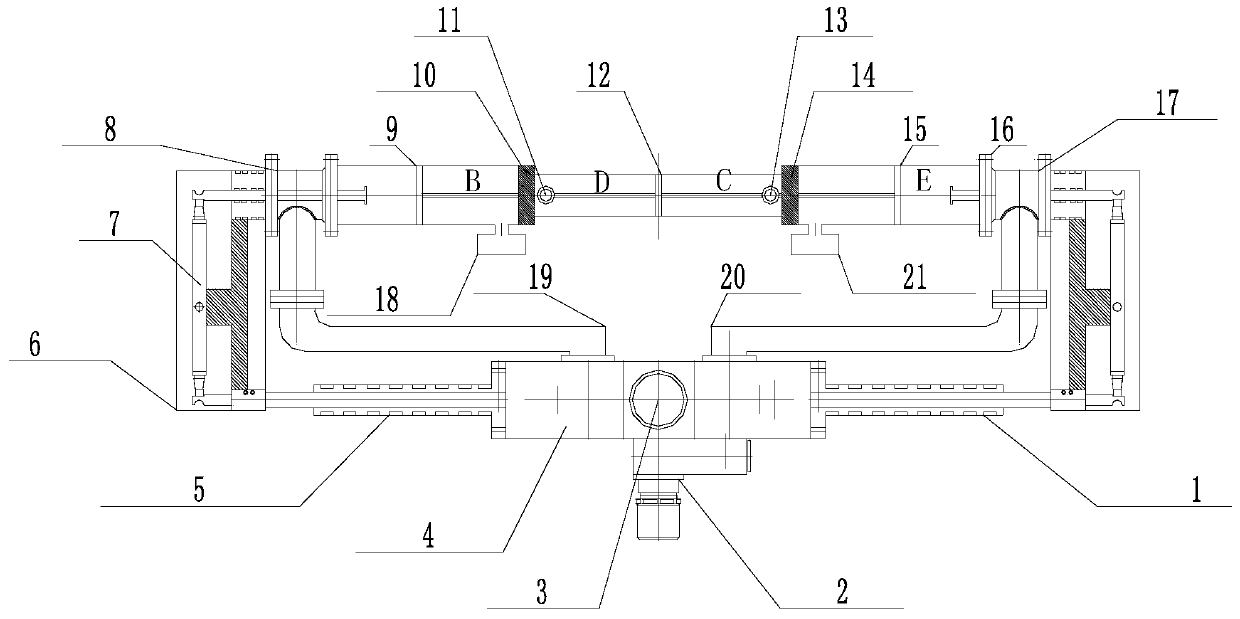
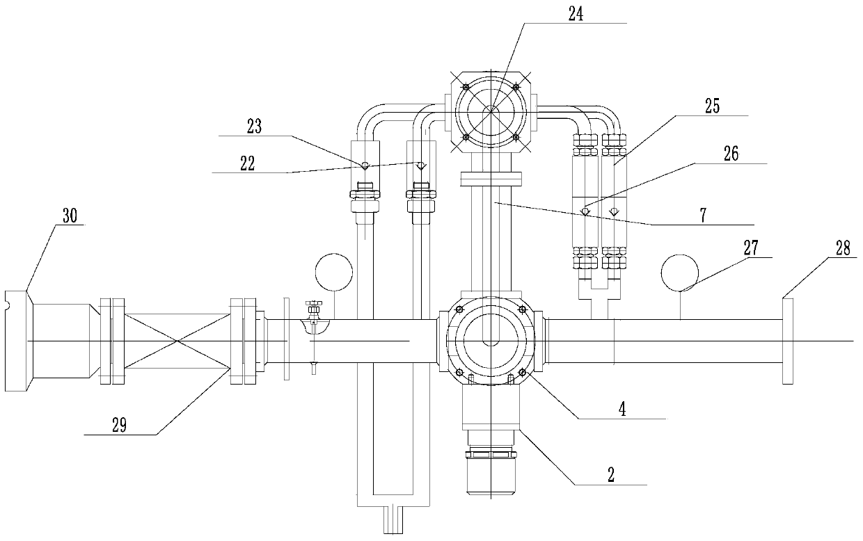
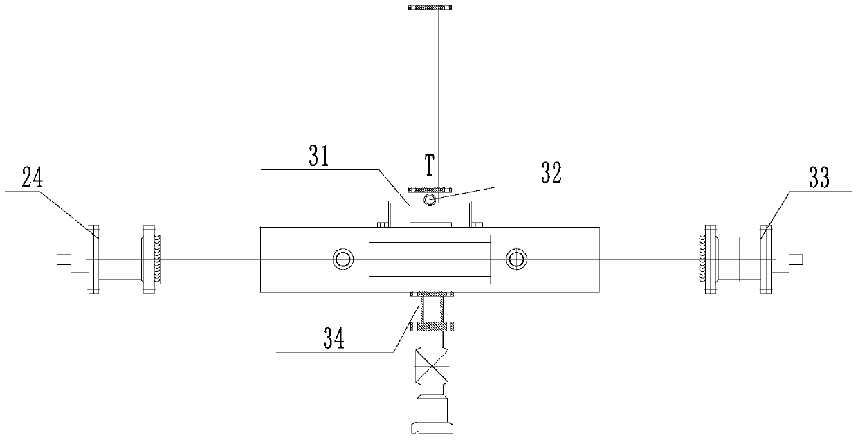
[0025] Concrete structure and working principle of the present invention refer to figure 1 , 2 , 3, 4 shown. In the present invention, the series-connected piston rod hydraulic cylinder is a working mode of staggered front and back, and reciprocating pumping. The outside of the hydraulic cylinder is connected by a cylinder flange 16, and the inner cylinder is guided by a bridge seal 10. The sleeves are connected, and the piston 9, piston 12, and piston 15 between the cylinders are connected in series through the bridge seal guide sleeve through the pull rod, and a liquid inlet tee is installed at the front and rear ends of the hydraulic cylinder. , that is, the left liquid inlet tee 8, the right liquid inlet tee 17, a stroke push rod sealer 24 is respectively provided on the left and right sides of the liquid inlet tee, and a push rod is respectively provided at the front and rear ends of the stroke push rod sealer 24 The reversing rocker arm frame 7 is provided with A and B...


PUM


Abstract

The invention discloses a self-control oil well casing gas recovery device, in which a liquid inlet tee and a stroke push rod sealer are respectively connected to the front and rear ends of a series-connected piston rod hydraulic cylinder; Between the stroke push rod sealer and the reversing push rod sealer at the left and right ends of the reversing valve; at the lower end of the hydraulic cylinder, there are A and B inlet and discharge manifolds; there are two upper parts of the intake check valve and the hydraulic cylinder The upper part of the two exhaust check valves is connected to the exhaust hole on the hydraulic cylinder, and the lower part is connected to the discharge three-way valve connected to the T port of the reversing valve. The liquid inlet check valve at the liquid inlet of the reversing valve P port is connected with the production discharge gate of the wellhead Christmas tree; the liquid discharge tee manifold at the liquid discharge manifold at the reversing valve T port is connected mains connection. The invention can effectively solve the phenomenon of oil well casing gas holding pressure for a long time, resulting in lower oil well fluid level, lower production capacity and gas lock.

Description

technical field [0001] The invention relates to the technical field of oil recovery in oil fields, in particular to a casing gas recovery device. Background technique [0002] In the middle and late stage of oilfield production and development, many oil production blocks have a certain amount of geological blocks with low permeability oil storage structure. The main characteristics are low production, low pressure of casing gas in oil wells, and it is difficult to use and recover casing gas in the production process. , part of the natural gas accumulates in the annular space of the oil casing, resulting in a decrease in the production capacity of the oil well. In severe cases, it will cause the phenomenon of "air lock", and the discharge will cause pollution to the atmosphere. At the same time, it also wastes precious and non-renewable clean resources. A vicious circle has formed. At present, most of the mature and applied products are constant pressure release valves, whic...

Claims


Application Information

Patent Timeline
Patent Type & Authority Patents(China)
IPC IPC(8): E21B43/00
Inventor 檀长江
Owner 檀长江
Why Eureka
Try Eureka