Self-controlled oil well casing gas recovery device

A recovery device and oil well casing technology, which is applied in wellbore/well components, production fluids, earth-moving drilling, etc., can solve the problems of oil well dynamic liquid level drop and production capacity reduction, so as to improve oil well production, eliminate pollution and harm human beings. The effect of harm, synergy and comprehensive economic benefits

Active Publication Date: 2017-06-23
檀长江
View PDF5 Cites 0 Cited by
  • Summary
  • Abstract
  • Description
  • Claims
  • Application Information

AI Technical Summary

Problems solved by technology

[0003] The purpose of the present invention is to provide a self-controlled oil well casing gas recovery device to solve the technical problems of oil well casing gas holding pressure for a long time, which leads to the decline of oil well fluid level, lower production capacity and gas lock phenomenon.

Method used


Image

  • Self-controlled oil well casing gas recovery device
  • Self-controlled oil well casing gas recovery device
  • Self-controlled oil well casing gas recovery device

Examples


Embodiment Construction

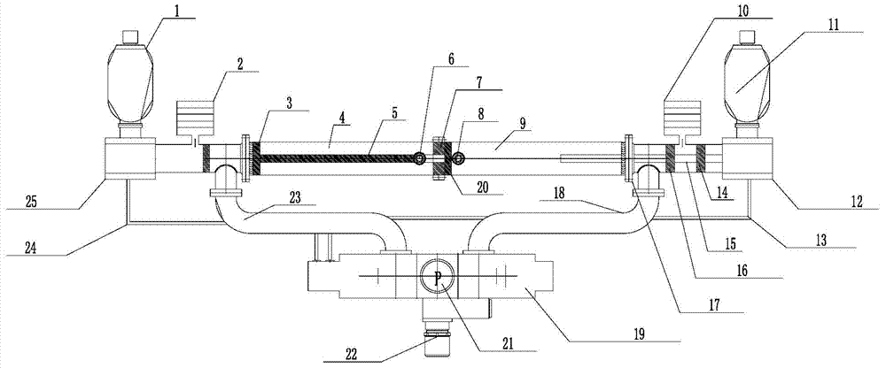
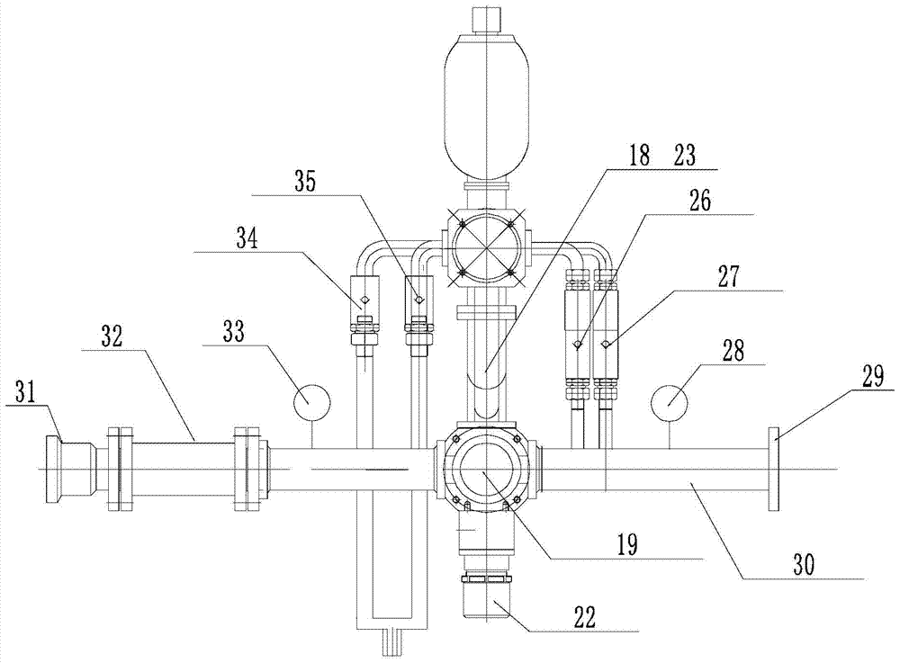
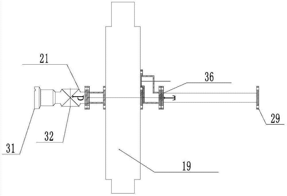
[0017] The specific structure of the present invention is shown in the accompanying drawings. see figure 1 , 2 As shown in the figure, the self-controlled oil well casing gas recovery device includes the first and second hydraulic cylinders 4 and 9 of the two-pole tie-rod piston connected in series, the hydraulic stroke cylinders 25 and 12 with accumulators 1 and 2, and the hydraulic integrated reversing. 19 and hydraulic oil pressure pipes 24 and 13. The first and second hydraulic cylinders 4 and 9 of the two-pole series-connected tie rod piston are in a working state of staggered extraction and discharge. The outside of the first hydraulic cylinder 4 and the second hydraulic cylinder 9 are connected through the cylinder flange 17, and A bridge seal 7 is provided between the first and second hydraulic cylinders. The pistons 3 and 20 of the first hydraulic cylinder 4 and the second hydraulic cylinder 9 are connected in series through the bridge seal 7 through the pull rod 5 ...


PUM


Abstract

The invention discloses an autocontrol type oil well casing pipe gas recycling device which comprises two stages of pull rod piston hydraulic cylinders connected with each other in series, hydraulic stroke oil cylinders with energy accumulators, a hydraulic integration commutator and a hydraulic oil pressure drawing pipe. The front ends and the rear ends of the two hydraulic cylinders are provided with two paths of original oil liquid inlet and outlet manifolds AB respectively and connected with liquid inlet and outlet holes AB in the upper portion of the hydraulic integration commutator. The end, with a union, of the front end of a P opening liquid inlet manifold one-way valve is connected with a union at the front end of a production liquid discharge gate on a wellhead oil extraction tree. A liquid discharge manifold flange at an opening T of the hydraulic integration commutator is connected with a production oil delivery main line. Intake check valves of the two hydraulic cylinders are connected with hollow pipe plugs at the front end of a well opening casing pipe gate. Exhaust check valves of the two hydraulic cylinders are connected with a T opening liquid discharge manifold. By means of the autocontrol type oil well casing pipe gas recycling device, the technical problems that due to long-term pressure building of an oil well casing pipe, the oil well movable liquid level drawdown productivity is lowered, and gas locking and other phenomena are caused can be solved.

Description

technical field [0001] The invention relates to the technical field of oil production in oil fields, in particular to a casing gas recovery device. Background technique [0002] In the middle and late stages of oilfield production and development, many oil production blocks have a certain amount of geological blocks with low-permeability oil storage structures, which are mainly characterized by low production and low casing gas pressure in oil wells, and it is difficult to use casing gas during the production process. After recovery, part of the natural gas accumulates in the annular space of the oil casing, resulting in a decrease in the production capacity of oil wells, and in severe cases, the phenomenon of "air lock" will occur. If it is discharged, it will cause pollution to the atmosphere and waste precious and non-renewable clean resources, forming a vicious circle. At present, most of the maturely used products are constant pressure vent valves, which have the chara...

Claims


Application Information

Patent Timeline
Patent Type & Authority Patents(China)
IPC IPC(8): E21B43/00
Inventor 檀长江
Owner 檀长江
Why Eureka
Try Eureka