Burner nozzle

A burner and nozzle technology, applied in the direction of burner, combustion method, combustion type, etc., to achieve the effect of sufficient combustion

Active Publication Date: 2015-12-23
HENAN HUIJIN INTELLIGENT EQUIP
View PDF10 Cites 1 Cited by
  • Summary
  • Abstract
  • Description
  • Claims
  • Application Information

AI Technical Summary

Problems solved by technology

[0004] In order to solve the technical problems existing in the existing burner nozzle, the present invention provides a burner nozzle with precise flame shape adjustment and sufficient pulverized coal combustion

Method used


Image

  • Burner nozzle
  • Burner nozzle
  • Burner nozzle

Examples


Embodiment Construction

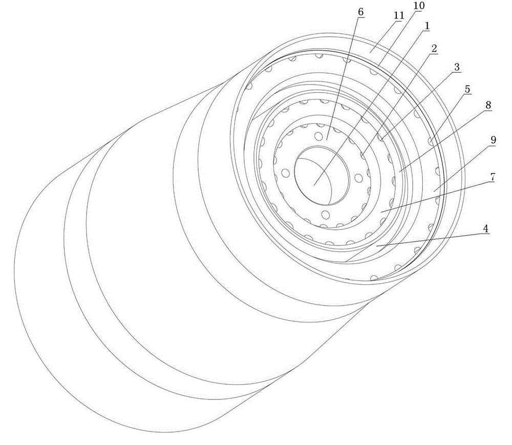
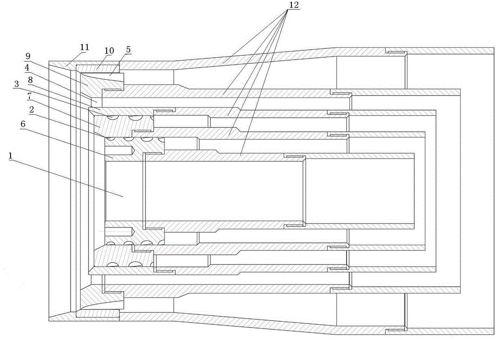
[0020] Depend on figure 1 , 2 As shown, a burner nozzle includes a flame cover 11, an outer axial wind head 10, an outer axial wind swirler 9, a pulverized coal wind head 8, a swirler 7, a swirl device 6 and a central oil injection port from the outside to the inside. 1. The outer axial flow duct 5 is formed between the outer axial wind head 10 and the outer axial wind cyclone 9, the pulverized coal air duct 4 is formed between the outer axial wind cyclone 9 and the pulverized coal wind head 8, and the pulverized coal wind head 8 and the A swirl air channel 3 is formed between the swirlers 7, a vortex air channel 2 is formed between the swirler 7 and the vortex device 6, and the interior of the vortex device 6 is an oil injection port 1, which is the oil injection port 1 of the central hole; figure 2 , 3 As shown, the outer shaft wind head 10, the outer shaft wind swirler 9, the pulverized coal wind head 8, and the swirler 7 pass through the outer shaft air duct, pulverized...


PUM


Abstract

A burner nozzle comprises an oil injection opening which is a center hole. An eddy air duct, a cyclone air duct, a pulverized coal air duct and an outer axial flow air duct are sequentially arranged outside the oil injection opening. All channels of the eddy air duct and the cyclone air duct are spiral channels with the same rotation direction. Each spiral channel is a conical spiral channel. The rotation direction of the conical spiral outer axial flow air duct is opposite to that of the cyclone air duct. Relatively-moving device telescopic joints are arranged between the inner cylindrical surfaces and the outer cylindrical surfaces of the outer axial flow air duct, the eddy air duct and the cyclone air duct of a burner body respectively. The inner cylindrical surfaces and the outer cylindrical surfaces of the eddy air duct, the cyclone air duct and the outer axial flow air duct, relatively move through the relatively-moving device telescopic joints. Not only is the rotation angle of sprayed air flow changed, but also the volume of the sprayed air flow is changed. The shape of sprayed flames can be adjusted better, particularly the rotation direction of the outer axial flow air duct is opposite to that of the cyclone air duct, so that turbulences are generated between the outer axial flow air duct and pulverized coal and between the cyclone air duct and the pulverized coal, and disordered powder of a pulverized coal layer can be burned more sufficiently.

Description

technical field [0001] The invention relates to the field of burners, in particular to burner nozzles. Background technique [0002] In the traditional cement production process, most of the simple single-channel and double-channel pulverized coal burners are used. These types of burners are mostly black and long, and the combustion efficiency is low; after the 1980s and 1990s, three-channel and four-channel burners were successively developed. Channel pulverized coal burner, but there is still the problem that the air duct structure design makes the air supply not stable enough, the flame shape and temperature are not easy to control, and cannot be adjusted in real time according to changes in the production environment and process conditions, and cannot adapt to uneven coal quality. The expansion joint is mainly used to compensate the expansion and contraction deformation of the pipeline due to temperature changes, and is also used to compensate the length of the pipeline ...

Claims


Application Information

Patent Timeline
Patent Type & Authority Applications(China)
IPC IPC(8): F23D1/02
Inventor 郭荣勋姜晓娟王付生宋万奎
Owner HENAN HUIJIN INTELLIGENT EQUIP
Why Eureka
Try Eureka