
Solar thermal collector

A technology of solar heat collectors and heat collecting tubes, which is applied in the field of solar heat collection, can solve the problems of reducing the service life of heat collectors, solar energy cannot be used elsewhere, and the existence of work losses, etc., to achieve simple structure, improve heat collection efficiency, reduce wasteful effect

Inactive Publication Date: 2015-12-23
广拓能源集团有限公司
View PDF8 Cites 4 Cited by
  • Summary
  • Abstract
  • Description
  • Claims
  • Application Information

AI Technical Summary

Problems solved by technology

[0003] However, in traditional solar collectors, the structures such as heat collecting tubes and reflective substrates are always exposed to the outside. Even when there is no need to work, the heat absorbing layer in the heat collecting tubes and the reflective substrate under the heat collecting tubes are always in a state of absorbing heat. Working loss, which reduces the service life of the collector
Furthermore, the solar water heaters in the prior art have a single function and can only realize light-to-heat conversion, that is, they only have the function of using solar energy to heat water instantly.
In this way, when the water in the solar water heater does not need to be reheated, the solar energy collected by it cannot be used elsewhere, or the water in the heat collecting tube can only be repeatedly heated meaninglessly, resulting in energy waste

Method used


Image

  • Solar thermal collector
  • Solar thermal collector

Examples


Embodiment Construction

[0026] The present invention will be further described in detail below in conjunction with the accompanying drawings, so that those skilled in the art can implement it with reference to the description.

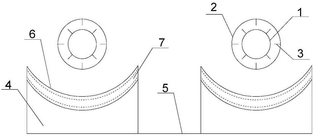
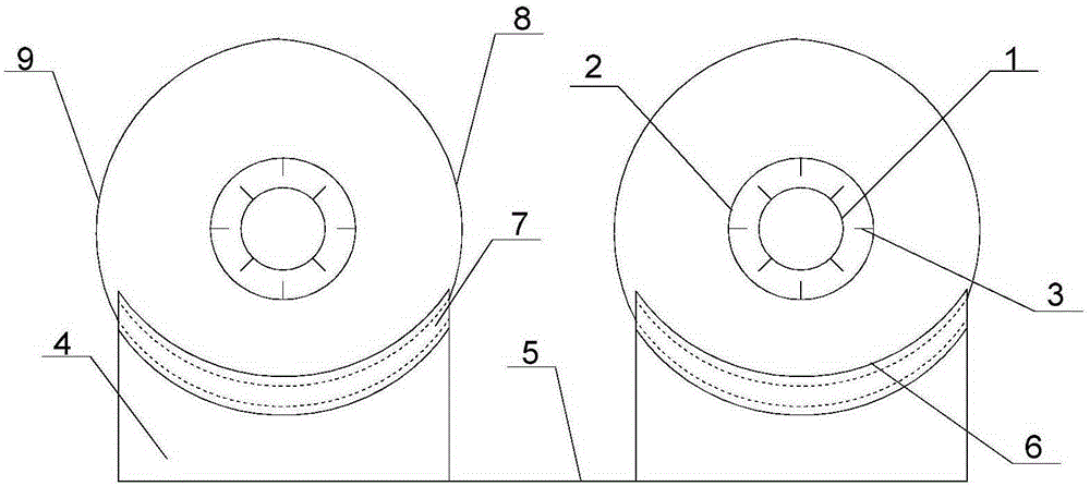
[0027] Such as Figure 1~2 Shown, the present invention provides a kind of solar thermal collector, comprises:

[0028] The heat collecting tube group includes a plurality of heat collecting tubes arranged side by side, the heat collecting tubes include a metal inner tube 1 and a glass outer tube 2 sleeved outside the metal inner tube 1, the outer wall of the metal inner tube 1 and the The inner wall of the glass outer tube 2 is provided with a plurality of fins 3, and the fins 3 are provided with a plurality of protrusions to increase the heating area, so that the heat-absorbing layer of the heat-collecting tube can store more heat energy and improve the heat-collecting tube. work efficiency;

[0029] The reflection plate is spliced ​​sequentially by a plurality of base bl...


PUM


Abstract

The invention discloses a solar thermal collector. The solar thermal collector comprises a thermal collection tube set, a reflection plate and a controller. The thermal collection tube set comprises a plurality of thermal collection tubes arranged side by side. The reflection plate is formed by splicing a plurality of base blocks and connecting plates in sequence, wherein the base blocks are arranged side by side. The upper surface of each base block is concave downwards to form an arc-shaped groove for containing the corresponding thermal collection tube. An arc-shaped reflection substrate is embedded in each arc-shaped groove. A through arc-shaped channel is formed in each base block and located below the corresponding arc-shaped groove. The upper surface and the lower surface of each arc-shaped channel are in sliding connection with a first arc-shaped sliding plate and a second arc-shaped sliding plate respectively in the arc direction. The controller is arranged to control the first arc-shaped sliding plates and the second arc-shaped sliding plates to slide in the arc-shaped channels. The solar thermal collector is simple in structure, convenient to use and practical. When water heating is not needed, the thermal collection tubes and the reflection substrates are covered, and meanwhile solar energy is converted into electric energy for storage and use, so that the economical use value of the solar thermal collector is increased, and the service life is prolonged.

Description

technical field [0001] The invention relates to the field of solar heat collection, in particular to a solar heat collector. Background technique [0002] The use of solar energy is mainly divided into two types, photothermal and photovoltaic, among which solar water heaters are typical of photothermal conversion and utilization. The heat collector of a solar water heater is usually composed of a heat collection tube and a reflective substrate. The heat collection tube is provided with a black or dark heat absorbing layer, which absorbs the heat of sunlight and is used to heat the water in the heat collection tube. The reflective substrate is located under the heat collecting tubes, and reflects the sunlight from the space between the heat collecting tubes back to the heat absorbing layer to improve the heat collecting efficiency. [0003] However, in traditional solar collectors, the structures such as heat collecting tubes and reflective substrates are always exposed to t...

Claims


Application Information

Patent Timeline
Patent Type & Authority Applications(China)
IPC IPC(8): F24J2/26F24J2/10F24J2/05F24J2/48H02S10/00F24S10/40F24S10/75F24S23/70
CPCY02E10/44Y02E10/50
Inventor 吕强
Owner 广拓能源集团有限公司
Learn More