Tea drying device capable of being hydraulically driven to lift

The technology of a tea drying device and a hydraulic lifting device is applied in the directions of drying, drying machine, drying gas arrangement, etc., which can solve the problems of difficult tea turning, uneven distribution of moisture, quality defects, etc., and achieves the improvement of air permeability. Effect

Active Publication Date: 2015-12-23
永新县恒龙农林开发有限公司
View PDF6 Cites 0 Cited by
  • Summary
  • Abstract
  • Description
  • Claims
  • Application Information

AI Technical Summary

Problems solved by technology

[0003] However, for the tea leaves during the entire drying process, the moisture distribution is often uneven, which often wastes more time to dry all the tea leaves for a uniform blowing drying device
Moreover, this uniform air blowing is often difficult to turn the tea leaves in a selected direction, and it is difficult to directly turn the side or bottom surface of the tea leaves.

Method used


Image

  • Tea drying device capable of being hydraulically driven to lift
  • Tea drying device capable of being hydraulically driven to lift
  • Tea drying device capable of being hydraulically driven to lift

Examples


Embodiment Construction

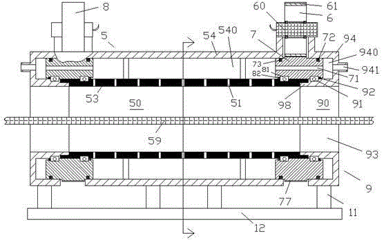
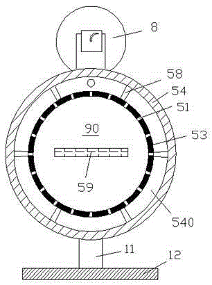
[0012] Combine below Figure 1-3 The present invention will be described in detail.

[0013] According to the embodiment, the hydraulically driven lifting tea drying device includes a structurally symmetrical drying air blowing device 5, and the drying air blowing device 5 includes a cylindrical air blowing and drying channel 50 extending axially. An annular body portion 53 and an annular housing portion 54 supported on said annular body portion 53 by a radial support 58 and accommodates said annular body portion 53, said annular body portion 53 is provided with A plurality of radial air blowing channels 51 are used to input the air flow along the radial direction of the cylindrical air blowing and drying channel 50, and the air blowing and drying channel 50 is used for a mesh conveyor belt 59 carrying tea leaves There is an annular airflow distribution chamber 540 between the annular shell part 54 and the annular body part 53, which is used to receive airflow input and distr...


PUM


Abstract

The invention discloses a tea drying device capable of being hydraulically driven to lift. The tea drying device comprises a dry airflow blowing device (5) with a bilaterally-symmetrical structure, wherein the dry airflow blowing device (5) comprises an annular body part (53) with an axially extended cylindrical air blowing and drying channel (50) and an annular shell part (54) which is supported on the annular body part (53) by a radial bracket (58) and is used for containing the annular body part (53); a plurality of radial air blowing channels (51) which are evenly distributed in the axial direction are formed in the annular body part (53) and are used for inputting the airflow along the radial direction of the cylindrical air blowing and drying channel (50).

Description

technical field [0001] The present application relates to the field of drying devices, in particular to a hydraulically driven lifting tea drying device. Background technique [0002] In some fields of drying machinery, especially in the field of tea drying machinery, air blowing is often used to blow away the moisture away from the vicinity of the tea leaves. In order to ensure that the tea leaves are fully and evenly dried, air blowing openings are often evenly arranged on the entire circumference of the drying device to blow around the entire periphery of the tea conveyor belt. [0003] However, for the tea leaves during the entire drying process, the moisture distribution is often uneven, which often wastes more time to dry all the tea leaves for a uniform blowing drying device . Moreover, this uniform air blowing is often difficult to cause the tea leaves to be turned in a selected direction, and it is difficult to directly turn the side or bottom surface of the tea l...

Claims


Application Information

Patent Timeline
IPC IPC(8): F26B17/04F26B21/04F26B25/00A23F3/06
Inventor 吴静
Owner 永新县恒龙农林开发有限公司
Why Eureka
Try Eureka