
Time domain reflection-type soil humidity sensor

A technology of soil moisture and time domain reflection, applied in the direction of using microwaves to measure moisture content, etc., can solve the problem of uneven monitoring accuracy of instruments

Inactive Publication Date: 2015-12-23
TIANJIN VOCATIONAL INST
View PDF0 Cites 3 Cited by
  • Summary
  • Abstract
  • Description
  • Claims
  • Application Information

AI Technical Summary

Problems solved by technology

At present, the main method of measuring soil moisture in my country's agricultural meteorological observation stations is the traditional drying method, and some stations have also deployed some automatic observation instruments for measurement, but the monitoring accuracy of various types of instruments is uneven, and it is not yet possible to measure soil moisture. Replace manual soil monitoring

Method used


Image

  • Time domain reflection-type soil humidity sensor
  • Time domain reflection-type soil humidity sensor
  • Time domain reflection-type soil humidity sensor

Examples


no. 1 example

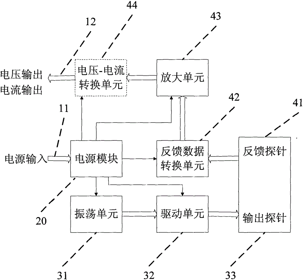
[0015] figure 1 Shown is a block diagram of the internal construction of the sensor according to the preferred embodiment of the present invention. At figure 1 Among them, the sensor includes a power supply module 20, an oscillation unit 31, a drive unit 32, an output probe 33, a feedback probe 41, a feedback data conversion unit 42, an amplification unit 43, a voltage-current conversion unit 44, a power input circuit 11 and a voltage / Current output line 12,. Wherein the voltage-current conversion unit 44 is an optional unit.

[0016] see figure 1 , the oscillation unit 31 outputs a 100MHz standard test frequency signal, which is added to the output probe 33 via the drive unit 32. According to different soil moisture conditions, the feedback probe 41 obtains a feedback signal related to the soil moisture condition. Through the feedback data conversion unit 42 , the amplifying unit 43 outputs a voltage signal related to the soil moisture condition, or outputs a current sig...

no. 2 example

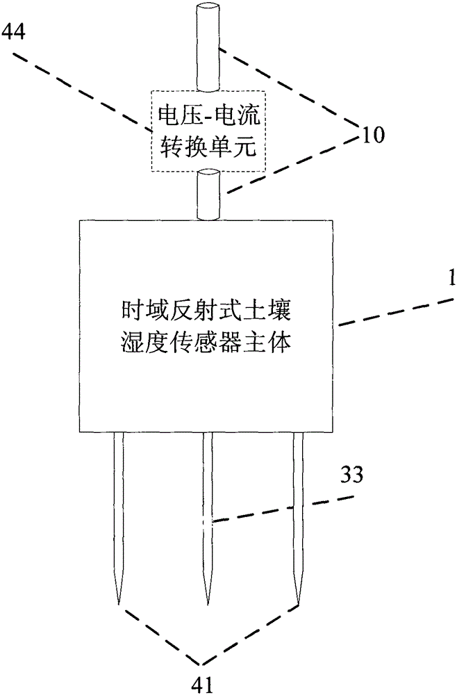
[0018] figure 2 Shown is a block diagram of a sensor according to a second embodiment of the present invention. At figure 2 Among them, the sensor includes a main body 1 of a time-domain reflective soil moisture sensor, an output probe 33 , a feedback probe 41 , a power supply and an output cable 10 and a voltage-current conversion unit 44 . Wherein the voltage-current conversion unit 44 is an optional unit.

[0019] see figure 2 The main body 1 of the time-domain reflective soil moisture sensor is potted with resin, the output probe 33 and the symmetrically distributed feedback probe 41 are stainless steel probes, which can effectively prevent soil, moisture and other substances from damaging the sensor unit and the probes. Influence, as an optional unit, the voltage-current conversion unit 44 is arranged outside the main body of the sensor, which can realize current or voltage output and is convenient for connecting various testing instruments.


PUM


Abstract

The invention provides a soil humidity sensor based on a time domain reflection principle, and the soil humidity sensor can realize rapid soil moisture measurement in a single-point single-depth mode or a multi-point multi-depth mode within a certain area range. The time domain reflection-type soil humidity sensor adopts current or voltage output and can be connected with various testing devices conveniently; the current output has quite strong anti-interference capability, so as to be in favor of long-distance transmission. The time domain reflection-type soil humidity sensor is convenient to apply; the sensor is only needed to be inserted into a PVC pipe which is embedded at a detected place in advance, and the measurement only needs a short time of a few seconds. The time domain reflection-type soil humidity sensor manufactured according to the figure 1 has the following function that through the measurement of a soil dielectric constant epsilon, the time domain reflection-type soil humidity sensor can realize rapid soil moisture measurement in the single-point single-depth mode or the multi-point multi-depth mode within a certain area range.

Description

technical field [0001] The invention relates to a soil moisture sensor, in particular to a time domain reflective soil moisture sensor. Background technique [0002] Soil moisture content is an important physical parameter of soil. Soil water is the link between surface water and groundwater. It plays an important role in the formation, transformation and consumption of water resources. The changes in the vegetation ecosystem on the pad surface are of great significance. At the same time, soil moisture content is also a key indicator of agricultural production conditions, and the soil moisture content plays a vital role in the growth of crops. The decomposition and mineralization of organic nutrients in the soil is inseparable from water. The chemical fertilizers applied to the soil can only be dissolved in water. The migration of nutrient ions to the surface of the root system and the absorption of nutrients by the crop roots must be achieved through the water medium, so i...

Claims


Application Information

Patent Timeline
IPC IPC(8): G01N22/04
Inventor 王彦苏彦莽张林中李爱军王向华李占昌王炯高博高本才
Owner TIANJIN VOCATIONAL INST
Learn More