
Thermal deformation test jig

A technology of thermal deformation and fixtures, which is applied in thermal analysis of materials, measuring devices, instruments, etc., can solve problems such as inaccurate test data, different fixture structures, and rolling back and forth of cables, so as to improve simplicity and beautiful appearance , easy-to-operate effects

Inactive Publication Date: 2015-12-23
WUXI XINHONGYE WIRE & CABLE
View PDF4 Cites 0 Cited by
  • Summary
  • Abstract
  • Description
  • Claims
  • Application Information

AI Technical Summary

Problems solved by technology

However, the principle of the cable thermal deformation test fixture in the national standard and UL and other foreign standards is the same as that in China, but the structure of the fixture is different, which leads to the need to replace the fixture used in the test when doing different standard tests. It takes a long time to warm up and the operation is very troublesome
At the same time, most of the traditional fixtures are made of copper materials. Although the temperature resistance is good, the surface is easily oxidized, resulting in inaccurate weight, and it is relatively heavy, so it is difficult to operate; The jig is easy to roll back and forth on the table, resulting in inaccurate test data

Method used


Image

  • Thermal deformation test jig

Examples


Embodiment Construction

[0017] Below the present invention will be further described in conjunction with the embodiment in the accompanying drawing:

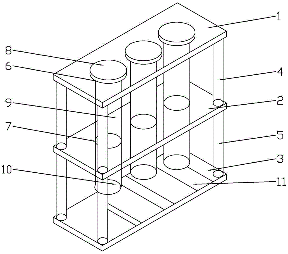
[0018] Such as figure 1 As shown, the present invention mainly includes a jig support and at least one pressure jig assembly, the jig support includes an upper partition 1, a middle partition 2 and a lower partition 3 arranged in parallel from top to bottom, the upper partition 1 and the middle partition The partition board 2 is connected into one body through a plurality of upper supporting columns 4 , and the middle partition board 2 and the lower partition board 3 are connected into one body through a plurality of lower supporting columns 5 .

[0019] Such as figure 1 In the shown embodiment, there are four upper support columns 4 , and the four upper support columns 4 are distributed at the four corners of the upper partition 1 and the middle partition 2 . There are four lower supporting columns 5 , and the four lower supporting columns 5 are dis...


PUM


Abstract

The invention relates to a cable test jig, in particular to a thermal deformation test jig, and belongs to the technical field of cable thermal deformation. The thermal deformation test jig comprises a jig support and at least one pressure jig assembly. The jig support comprises an upper separation plate, a middle separation plate and a lower separation plate which are arranged in parallel from top to bottom. The upper separation plate is provided with a plurality of upper separation plate guide holes, the middle separation plate is provided with middle separation plate guide holes with the number the same as that of the upper separation plate guide holes, and each middle separation plate guide hole is located under one corresponding upper separation plate guide hole. Each pressure jig assembly is arranged in one corresponding set of upper separation plate guide hole and lower separation plate guide hole of the jig support. The UL standard and domestic standard test needs can be met at the same time, the time of a test is greatly shortened, and operation simplicity is improved. A plurality of V-shaped locating grooves are formed in the lower separation plate, and cables are placed in the locating grooves and are not prone to roll.

Description

technical field [0001] The invention relates to a cable test fixture, in particular to a thermal deformation test fixture, which belongs to the technical field of cable thermal deformation. Background technique [0002] At present, the cable thermal deformation test in the cable industry is done according to the standards referred to by the cable, and the fixtures used in the test are also determined according to the standards. There are all technical theories, test methods and test fixtures. is uniform. However, the principle of the cable thermal deformation test fixture in the national standard and UL and other foreign standards is the same as that in China, but the structure of the fixture is different, which leads to the need to replace the fixture used in the test when doing different standard tests. Cause warm-up time is longer, operation is very troublesome. At the same time, most of the traditional fixtures are made of copper materials. Although the temperature res...

Claims


Application Information

Patent Timeline
IPC IPC(8): G01N25/00
Inventor 朱长康刘坤瑜关勇
Owner WUXI XINHONGYE WIRE & CABLE
Learn More