
A display and coloring method thereof

A display and display unit technology, which is applied in the direction of instruments, electric solid-state devices, semiconductor devices, etc., can solve the problems of display panel bright lines, excessive brightness, and dark state deterioration, so as to avoid dark state deterioration and screen bright lines , the effect of brightness enhancement

Active Publication Date: 2017-12-29
XIAMEN TIANMA MICRO ELECTRONICS +1
View PDF8 Cites 0 Cited by
  • Summary
  • Abstract
  • Description
  • Claims
  • Application Information

AI Technical Summary

Problems solved by technology

However, the subsequent increase in data lines or scanning lines also increases the difficulty of manufacturing
Also, this approach often results in much higher brightness than is actually needed and can lead to poor dark states
In the traditional WRGB design, the sub-pixel arrangement is usually RGBW repeated arrangement, which makes the W pixels form a continuous arrangement in a certain direction, which will lead to bright lines on the display panel.

Method used


Image

  • A display and coloring method thereof
  • A display and coloring method thereof
  • A display and coloring method thereof

Examples


Embodiment Construction

[0017] The present disclosure will be further described in detail below with reference to the drawings and embodiments. It should be understood that the specific embodiments described here are only used to explain the present invention, rather than to limit the present invention. In addition, it should be noted that, for the convenience of description, only the parts related to the present invention are shown in the drawings. Throughout this specification, the same or similar reference numerals represent the same or similar structures, elements or processes. It should be noted that, in the case of no conflict, the features in the embodiments of the present disclosure may be combined with each other. The present disclosure will be described in detail below with reference to the drawings and embodiments.

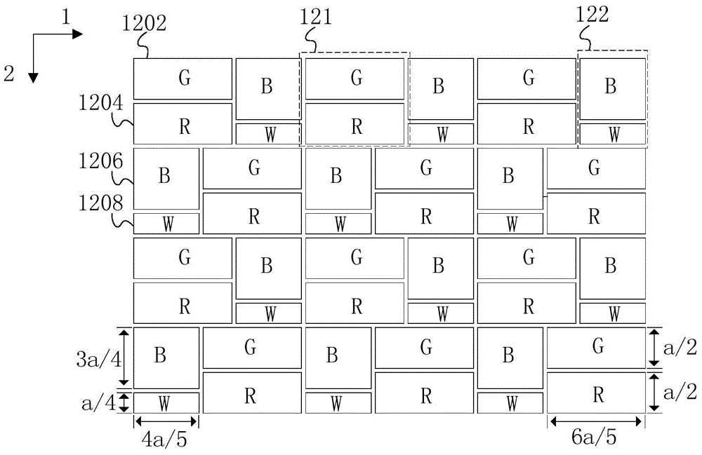
[0018] figure 1 An example of a pixel array of a display according to an embodiment of the present disclosure is shown. Such as figure 1 As shown, the pixel array include...


PUM


Abstract

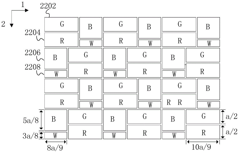
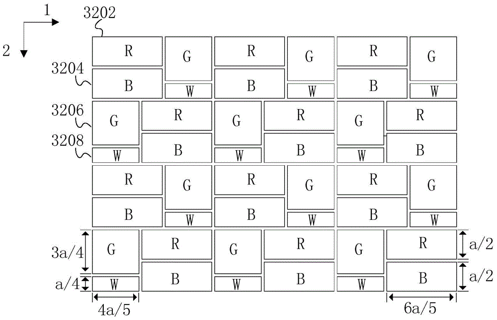
The disclosure of the present invention provides a display, which includes a pixel array, the pixel array includes: a first pixel group and a second pixel group, and the first pixel group and the second pixel group are alternately arranged at intervals in the first direction and the second direction , where the first direction is perpendicular to the second direction; the sum of the lengths of the first pixel group and the second pixel group in the first direction is twice the length of the first pixel group in the second direction, and the first pixel group The length in the second direction is equal to that of the second pixel group; the first pixel group includes a first sub-pixel and a second sub-pixel, and the second pixel group includes a third sub-pixel and a fourth sub-pixel; the first sub-pixel, the second The areas of the second sub-pixel and the third sub-pixel are equal, and the area of ​​the fourth sub-pixel is smaller than the area of ​​the first sub-pixel; wherein the first sub-pixel, the second sub-pixel, the third sub-pixel and the fourth sub-pixel are configured differently color.

Description

technical field [0001] The present disclosure relates to the display field, in particular, to a display and a coloring method thereof. Background technique [0002] Pixel density is an important indicator of a display, which is defined as the number of pixels that can be displayed per unit area. The higher the pixel density, the more delicate the image displayed on the display and the more details it displays. Generally, a common method for increasing the pixel density of a display is to increase the number of sub-pixels per unit area of ​​the display panel. The number will also increase accordingly, which increases the difficulty of manufacturing and reduces the yield rate of display production, and the increase of data lines or scanning lines will inevitably reduce the pixel aperture ratio on the display panel, so that the display's Display brightness decreases. [0003] The traditional WRGB design introduces W sub-pixels on the basis of RGB three-color sub-pixels to inc...

Claims


Application Information

Patent Timeline
Patent Type & Authority Patents(China)
IPC IPC(8): G09F9/30G02F1/1335H01L27/32
Inventor 张静丽张沼栋
Owner XIAMEN TIANMA MICRO ELECTRONICS
Learn More