Shift register unit and a drive method, a shift register and a display device thereof

A technology of a shift register and a driving method, which is applied in static memory, digital memory information, instruments, etc., can solve problems such as insufficient opening, reduced display effect of a display device, and uneven display of a display device, so as to achieve uniform display and improve display effect of effect

Active Publication Date: 2015-12-23
BOE TECH GRP CO LTD
View PDF6 Cites 21 Cited by
  • Summary
  • Abstract
  • Description
  • Claims
  • Application Information

AI Technical Summary

Problems solved by technology

[0003] However, the input module in the shift register unit includes a transistor, and the transistor has a threshold voltage, and the threshold voltage of the transistor of the input module in each shift register unit manufactured in the manufacturing process is often different, and the threshold voltage of the transistor that drifts toward the positive direction Under the action of the trigger signal, the phenomenon of insufficient turn-on is prone to occur. The influence of the threshold voltage makes the tim

Method used


Image

  • Shift register unit and a drive method, a shift register and a display device thereof
  • Shift register unit and a drive method, a shift register and a display device thereof
  • Shift register unit and a drive method, a shift register and a display device thereof

Examples


Embodiment 1

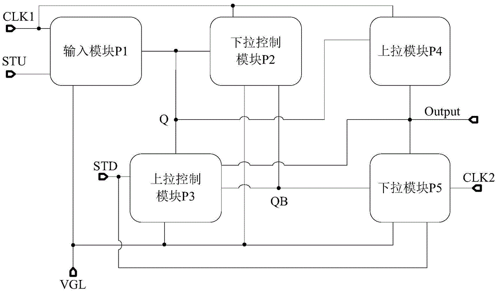
[0028] see figure 1 , The shift register unit provided by the embodiment of the present invention includes an input module P1, a pull-down control module P2, a pull-up control module P3, a pull-up module P4 and a pull-down module P5. Wherein, the input module P1 is connected with the first trigger signal terminal STU, the first clock signal terminal CLK1, the low level terminal VGL and the pull-up control node Q, and the input module P1 is used to utilize the bootstrap effect to convert the first trigger signal terminal STU to Signal without threshold voltage V th The lossy ground is transmitted to the pull-up control node Q, and the voltages of the gate-on signal and the first pole-on signal of the transistor in the input module are both V1 (high level signal), and the gate-off signal and the first pole open signal of the transistor in the input module are The voltage of one pole off signal is V2 (low level signal), and the voltage of the signal transmitted to the pull-up co...

Embodiment 2

[0041] see Figure 4 The specific structures of the input module P1, the pull-down control module P2, the pull-up control module P3, the pull-up module P4 and the pull-down module P5 in the first embodiment will be described in detail below.

[0042] The input module P1 includes a first transistor T1, a second transistor T2, a third transistor T3, and a first capacitor C1; wherein, the gate of the first transistor T1 is connected to the first trigger signal terminal STU, and its first pole is connected to the second The second pole of the transistor T2 is connected to the first pole of the first capacitor C1, and the second pole thereof is connected to the first trigger signal terminal STU;

[0043] The gate of the second transistor T2 is connected to the first clock signal terminal CLK1, its first pole is connected to the low-level terminal VGL, and its second pole is connected to the first pole of the first capacitor C1;

[0044] The gate of the third transistor T3 is conne...

Embodiment 3

[0071] An embodiment of the present invention provides a shift register, which is characterized in that it includes a multi-stage shift register unit as described in the above embodiment, and the shift register unit in the shift register is the same as the shift register unit in the above embodiment. The bit register unit has the same advantages, which will not be repeated here.


PUM


Abstract

The invention discloses a shift register unit and a drive method, a shift register and a display device thereof, relates to the technical field of display, and aims at solving the problems that the display device is uneven in display, and poor in display effect. The shift register unit comprises an input module, a pull-down control module, a pull-up control module, a pull-up module and a pull-down module, wherein the input module is connected with a first trigger signal port, a first clock signal port, a low level port and a pull-up control node; the input module is used for transmitting a signal of the first trigger signal port to the pull-up control node by a bootstrap effect without threshold voltage loss. The shift register unit disclosed by the invention is applied to the display device.

Description

technical field [0001] The invention relates to the field of display technology, in particular to a shift register unit, a driving method thereof, a shift register and a display device. Background technique [0002] When the display device is displaying, it is necessary to use a shift register to scan the pixel unit. The shift register includes a plurality of shift register units, and each shift register unit corresponds to a row of pixel units to provide gate drive signals for the pixel units. Therefore, the progressive scan driving of the pixel units of the display device is realized by a plurality of shift register units to display images. [0003] However, the input module in the shift register unit includes a transistor, and the transistor has a threshold voltage, and the threshold voltage of the transistor of the input module in each shift register unit manufactured in the manufacturing process is often different, and the threshold voltage of the transistor that drifts...

Claims


Application Information

Patent Timeline
IPC IPC(8): G09G3/20G11C19/28
CPCG11C19/28G11C19/184G09G3/3677G09G3/3266G09G2310/0286G09G3/3674G09G2310/06G09G2310/08G09G2320/0233G09G2320/045
Inventor 李全虎李永谦孟松
Owner BOE TECH GRP CO LTD
Why Eureka
Try Eureka