Supercharge Your Innovation With Domain-Expert AI Agents!

Grid drive substrate and liquid crystal display employing same

A gate drive and substrate technology, applied in static indicators, instruments, static memories, etc., can solve problems such as increasing design complexity, and achieve the effect of reducing the number of wires and simplifying the complexity

Active Publication Date: 2015-12-23
WUHAN CHINA STAR OPTOELECTRONICS TECH CO LTD
View PDF9 Cites 5 Cited by
  • Summary
  • Abstract
  • Description
  • Claims
  • Application Information

AI Technical Summary

Problems solved by technology

However, using two start signals STV1 and STV2 requires more wires to transmit signals, increasing the complexity of the design

Method used


Image

  • Grid drive substrate and liquid crystal display employing same
  • Grid drive substrate and liquid crystal display employing same
  • Grid drive substrate and liquid crystal display employing same

Examples


Embodiment Construction

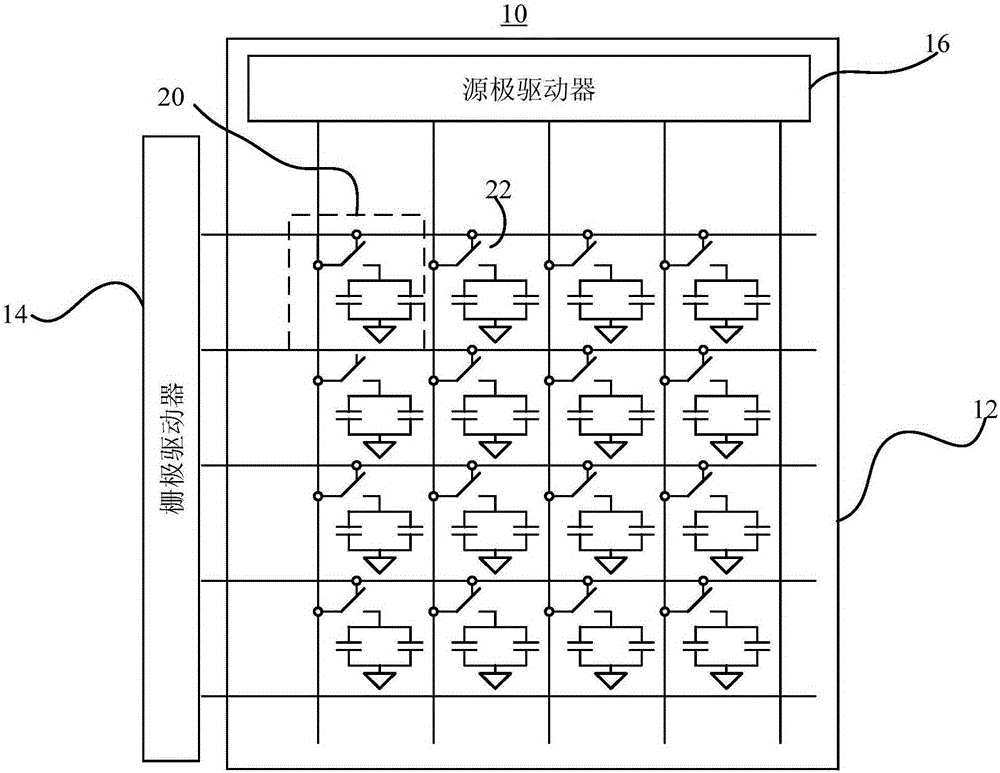
[0023] see figure 1 , figure 1 It is a functional block diagram of the liquid crystal display 10 of the present invention. The liquid crystal display 10 includes a gate driving substrate 14 and a source driver (source driver) 16 . The gate driving substrate 14 includes a plurality of pixels arranged in a matrix, and each pixel includes three pixel units 20 respectively representing three primary colors of red, green, and blue (RGB). Taking a liquid crystal display 10 with a resolution of 1024×768 as an example, a total of 1024×768×3 pixel units 20 are required to be combined. The gate drive substrate 14 outputs scanning signals to turn on the transistors 22 in each row sequentially, and at the same time, the source driver 16 outputs corresponding data signals to a whole column of pixel units 20 to charge them to their respective required voltages to display different grayscale. When the charging of the same row is completed, the gate drive substrate 14 will turn off the sc...


PUM


Abstract

The invention discloses a grid drive substrate, and the substrate comprises N shift buffer memory units. Each M shift buffer memory units are controlled by M clock signals. The first shift buffer memory unit is used for outputting a scanning signal pulse at an output end according to the first clock signal and a starting signal, and the last shift buffer memory unit is used for outputting a scanning signal pulse at the output end according to the M-th clock signal and the starting signal. The frequency of the starting signal is equal to the updating frequency of an image frame. The pulse width of the starting signal starts from a drop edge of the M-th clock signal applied to the last shift buffer memory unit when a first image frame is scanned, and ends at a rise edge of the first clock signal applied to the first shift buffer memory unit when a second image frame is scanned. Because the first and last shift buffer memory units are driven to output the scanning signal pulses according to the starting signal, the substrate can reduce the number of wires for transmitting the starting signal, and reduces the complexity of layout design.

Description

technical field [0001] The present invention relates to a liquid crystal display, especially a liquid crystal display using a gate drive (Gated driver on array, GOA) substrate. Background technique [0002] The GOA circuit utilizes the thin film transistor liquid crystal display Array process to fabricate the gate driver on the gate drive substrate with a thin film transistor (Thinfilm transistor, TFT) array, so as to realize the driving mode of progressive scanning. [0003] The GOA circuit includes several shift register units, each shift register unit consists of a pull-up circuit (Pull-up circuit), a pull-up control circuit (Pull-up control circuit), a pull-down circuit (Pull-down circuit), a pull-down hold circuit (Pull- downHoldingcircuit), and a boost circuit (Boostcircuit) responsible for potential uplift. [0004] The pull-up circuit is mainly responsible for outputting the input clock signal (Clock) to the gate of the thin film transistor as a driving signal of th...

Claims


Application Information

Patent Timeline
Patent Type & Authority Applications(China)
IPC IPC(8): G09G3/36
CPCG09G3/3677G09G2300/0426G09G2300/0809G09G2310/0286G11C19/184G11C19/28
Inventor 李亚锋
Owner WUHAN CHINA STAR OPTOELECTRONICS TECH CO LTD
Features
  • R&D
  • Intellectual Property
  • Life Sciences
  • Materials
  • Tech Scout
  • Unparalleled Data Quality
  • Higher Quality Content
  • 60% Fewer Hallucinations
Learn More