Shift register unit, driving method therefor, grid drive circuit, and display device

A gate drive circuit, shift register technology, applied in static memory, digital memory information, instruments, etc., can solve the problems of normal display, easy interference of display signals, and inability to touch normally, so as to achieve touch and Display, achieve the effect of mutual compatibility and avoid mutual interference

Active Publication Date: 2015-12-23
BOE TECH GRP CO LTD +1
View PDF5 Cites 60 Cited by
  • Summary
  • Abstract
  • Description
  • Claims
  • Application Information

AI Technical Summary

Problems solved by technology

In the embedded touch screen, because the touch electrodes are very close to the grid, grid lines and data lines, the touch signal and display signal are likely to interfere with each other when the touch and display are performed simultaneously, resulting in failure to touch or display normally.

Method used


Image

  • Shift register unit, driving method therefor, grid drive circuit, and display device
  • Shift register unit, driving method therefor, grid drive circuit, and display device
  • Shift register unit, driving method therefor, grid drive circuit, and display device

Examples


Embodiment 1

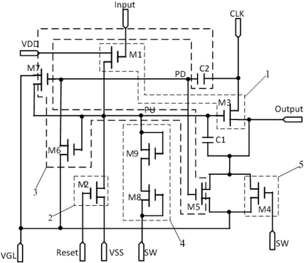
[0045] This embodiment provides a shift register unit, such as figure 1 As shown, it includes a pull-up module 1, a pull-down module 2, a first capacitor C1 and a first noise release module 3, and also includes a compensation module 4; a pull-up module 1, a pull-down module 2, a first noise release module 3, and a compensation module 4 and the first terminal of the first capacitor C1 is connected to the pull-up node PU; the pull-up module 1, the first noise releasing module 3 and the second terminal of the first capacitor C1 are connected to the output terminal Output of the shift register unit. The pull-up module is configured to pull up the signal output from the output terminal Output of the shift register unit according to the start signal input from the start signal input terminal Input. The pull-down module 2 is configured to pull down the signal output from the output terminal Output of the shift register unit according to the reset signal input from the reset signal in...

Embodiment 2

[0067] This embodiment provides a driving method for a shift register unit. The difference from the driving method in Embodiment 1 is that the touch phase is inserted into the end of the first phase in the driving process of any shift register unit in one frame scan. .

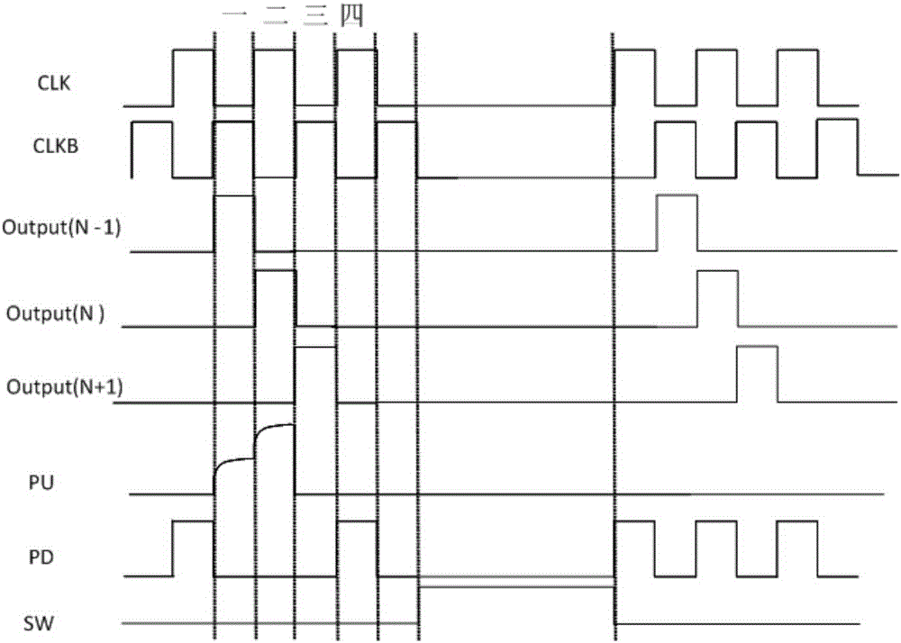
[0068] Such as image 3 As shown, when the first stage ends, the touch switch terminal SW inputs a high level signal, the clock signal terminal CLK becomes low level, and the pull-up node PU continues to maintain a high level; since the touch switch terminal SW is at a high level Therefore, the fourth transistor M4 is turned on to release noise to the output terminal Output of the shift register unit, and the output terminal Output will not output the gate drive signal, thereby avoiding the interference of the gate drive signal on the touch signal and ensuring the touch control signal. normal operation of the control function. At the same time, since the pull-up node PU is at a high level, the input of the t...

Embodiment 3

[0071]This embodiment provides a driving method for a shift register unit. The difference from the driving method in Embodiment 1-2 is that the touch phase is inserted into the second phase of the driving process of any shift register unit in one frame scan. When it ends.

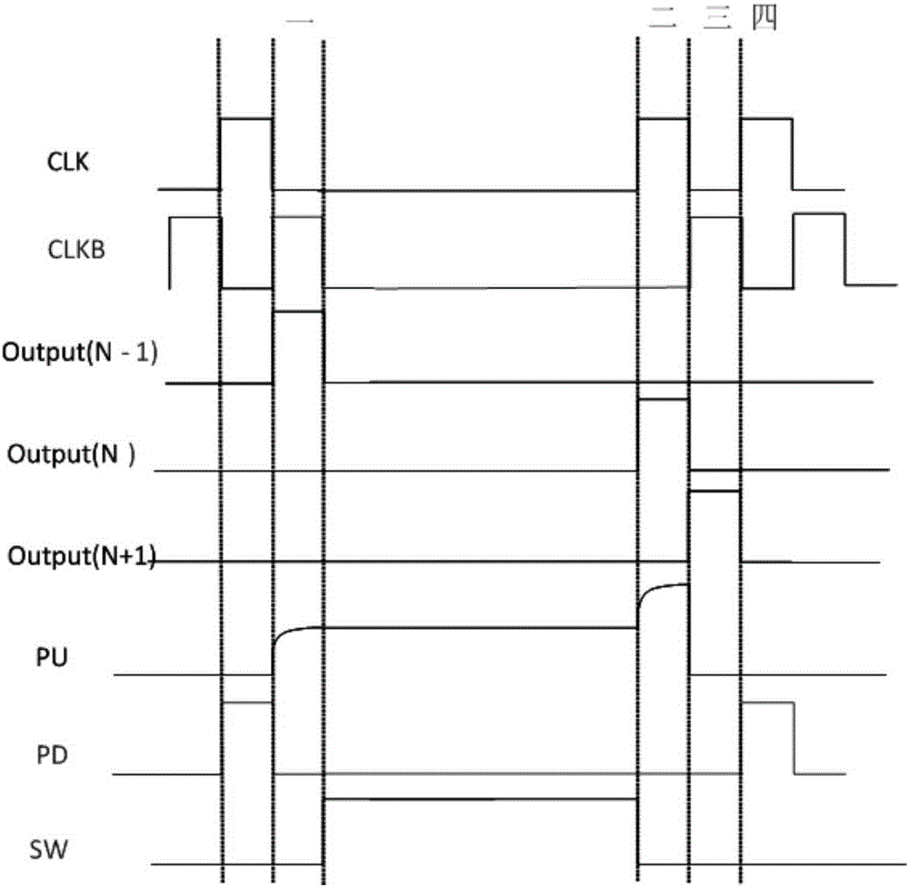
[0072] Such as Figure 5 As shown, when the second stage ends, the touch switch terminal SW inputs a high level signal, the clock signal terminal CLK becomes low level, and the pull-up node PU continues to maintain a high level; since the touch switch terminal SW is at a high level Therefore, the fourth transistor M4 is turned on to release noise to the output terminal Output of the shift register unit, and the output terminal Output will not output the gate drive signal, thereby avoiding the interference of the gate drive signal on the touch signal and ensuring the touch control signal. normal operation of the control function. At the same time, since the pull-up node PU is at a high level, the input of ...


PUM


Abstract

The invention provides a shift register unit, a driving method therefor, a grid drive circuit, and a display device. The shift register unit comprises a pull-up module, a pull-down module, a first capacitor, a first noise amplification module, and a compensation module. The pull-up module is used for the pulling-up of a signal outputted by the shift register unit according to a starting signal inputted by a starting signal input end. The pull-down module is used for the pulling-down of a signal outputted by the shift register unit according to a reset signal inputted by a reset signal input end. The first capacitor is used for improving the potential of a pull-up node at a pull-up stage. The first noise amplification module is used for noise amplification of the signal outputted by the shift register unit at a pull-down stage. The compensation module is used for the potential compensation of the pull-up node at a touch stage according to a touch control switching signal inputted by a touch control switching end. The shift register unit can avoid mutual interference between embedded type touch display screen drive and display drive, and achieves that the embedded type touch display screen drive and display drive are compatible with each other.

Description

technical field [0001] The present invention relates to the field of display technology, in particular to a shift register unit, a driving method thereof, a gate driving circuit and a display device. Background technique [0002] With the development of flat panel display, high resolution and narrow bezel become the trend of development, and to realize high resolution and narrow bezel display, integrating gate drive circuit on the panel is the most important solution. [0003] As the touch screen (TouchPanel) gradually enters people's life, the previous input devices are gradually eliminated from people's field of vision. Many types of input devices are currently available for performing operations in computer systems, such as mice, buttons, touch panels, joysticks, touch screens, and the like. And touchscreens are becoming more and more popular due to their ease of use, operational versatility, falling prices, and steadily increasing yields. [0004] The touch screen can ...

Claims


Application Information

Patent Timeline
Patent Type & Authority Applications(China)
IPC IPC(8): G09G3/36G11C19/00G11C19/28
CPCG06F3/0412G06F3/04184G09G3/2092G09G2310/0267G09G2310/0286G09G2310/08G09G2330/06G09G3/3648G09G2300/0426G09G2310/0251G09G2310/0283
Inventor 古宏刚李小和邵贤杰刘波宋洁
Owner BOE TECH GRP CO LTD
Why Eureka
Try Eureka